a roll cutting machine

A rolling cutting machine and cutting knife technology, applied in the direction of shearing device, shearing machine equipment, metal processing equipment, etc., can solve the problems of large occupied area, troublesome assembly and debugging, etc., and achieve small occupied area and good product quality , large size effect

Active Publication Date: 2017-12-29
浙江安浦科技有限公司
View PDF12 Cites 0 Cited by
  • Summary
  • Abstract
  • Description
  • Claims
  • Application Information

AI Technical Summary

Problems solved by technology

However, this unit cannot be adapted to cutting plates of other materials, and the unit occupies a large area, which makes assembly and debugging troublesome.

Method used


Image

  • a roll cutting machine
  • a roll cutting machine
  • a roll cutting machine

Examples


Embodiment

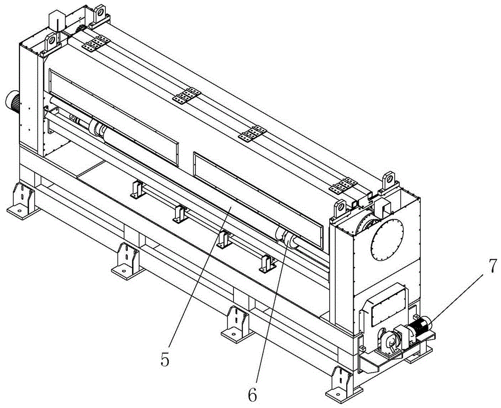
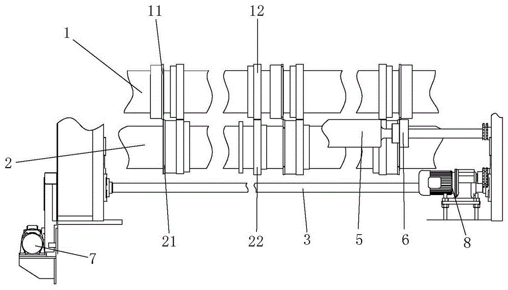
[0029] Example: such as figure 1 and figure 2 As shown, a hobbing machine includes an upper roll 1, a lower roll 2, a main shaft 3, an input roll 4 and an output roll 5. Upper roll 1 is provided with three upper ring knives 11 co-rotating with upper roll 1, and lower roll 2 is provided with three lower ring knives 21 co-rotating with lower roll 2, each upper ring knives 11 and Corresponding to it, the cutting edge of the lower ring knife 21 is opposite to form a cutting knife group. The hobbing machine is provided with three groups of cutting knife groups, wherein two groups are arranged at the two ends of the upper roller 1 and the lower roller 2, and the other group is arranged at the middle of the upper roller 1 and the lower roller 2.

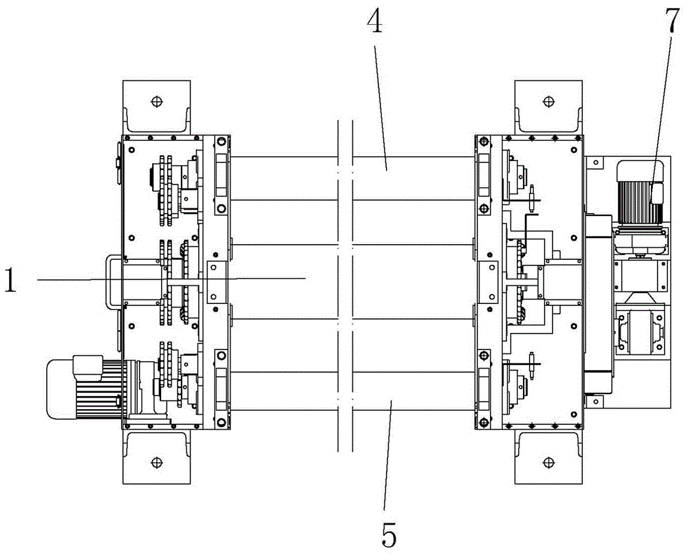
[0030] Such as Figure 4 As shown, both the upper roll 1 and the lower roll 2 are actively rotating rolls, both ends of the upper roll 1 are installed through eccentric bushings, and the left and right ends maintain the same eccentric d...


PUM


Abstract

The invention relates to a slitting mill, and belongs to the technical field of thin plate cutters. The slitting mill comprises an upper roller and a lower roller, and further comprises at least two upper ring cutters arranged on the upper roller and rotating with the upper roller, and at least two lower ring cutters arranged on the lower roller and rotating with the lower roller, wherein the upper roller and the lower roller are both rollers actively rotating; and each upper ring cutter and the corresponding lower ring cutter are opposite in edges to form a cutter set. Through mutual fit between the ring cutters mounted on the upper roller and the lower roller, the slitting mill can realize longitudinal cutting of various plates, can perform fixed-width treatment for the plates, can cut copper foil substrates, paper substrates, aluminum substrates and the like, and has the advantages of quick cutting speed and good cutting effect.

Description

technical field [0001] The invention relates to a rolling cutting machine, which belongs to the technical field of sheet cutting machines. Background technique [0002] Roll cutting machines are widely used in many fields, mainly for cutting cardboard, plastic board and metal board. In the copper clad laminate manufacturing industry, the previous technology generally adopts the method of upper knife and lower cutting or lower knife upper cutting, that is, the lower knife is fixed and the upper knife is cut lower or the upper knife is fixed and the lower knife is upper cut to achieve cutting. This technique does not have high requirements for equipment, so the purchase cost is low; but its production efficiency is low, and it also has requirements for the cut boards, and cannot adapt to the cutting of harder boards. [0003] The application number is a utility model disclosed by CN200920139165.1, which discloses a numerical control veneer hobbing and cutting machine. Connec...

Claims


Application Information

Patent Timeline
Patent Type & Authority Patents(China)
IPC IPC(8): B23D19/06
CPCB23D19/06
Inventor 周灵珍支鹏飞
Owner 浙江安浦科技有限公司
Why Eureka
Try Eureka