Combined vertical wear-resistant roller

A grinding roller and vertical technology, applied in grain processing and other directions, can solve the problems of low wear resistance of ductile metal parts, inability to achieve disassembly, and reduced use value, and achieve the effect of strong connection strength, reduction of processing difficulty, and avoidance of waste.

Active Publication Date: 2016-01-06
CHONGQING LUOMAN NEW MATERIAL TECH CO LTD
View PDF7 Cites 2 Cited by
  • Summary
  • Abstract
  • Description
  • Claims
  • Application Information

AI Technical Summary

Problems solved by technology

[0002] The rapid development of modern industry has made equipment have higher requirements on the wear resistance of components, such as grinding rollers, grinding discs and crusher blow bars of vertical mills used in cement, mining, metallurgy, power stations or various similar industries etc. The hardness and toughness of traditional steel materials are usually contradictory. The existing technology mostly uses bimetallic composite and ceramic metal composite technology to improve the wear resistance of the material. After the main wear-resistant parts of such products are completely consumed, the tough metal parts are The wear resistance is low and the use value is reduced, but because it is connected with the wear-resistant part through metallurgy, it cannot be disassembled, and it is usually treated as waste, which will cause a lot of waste of resources

Method used


Image

  • Combined vertical wear-resistant roller
  • Combined vertical wear-resistant roller
  • Combined vertical wear-resistant roller

Examples


Embodiment 1

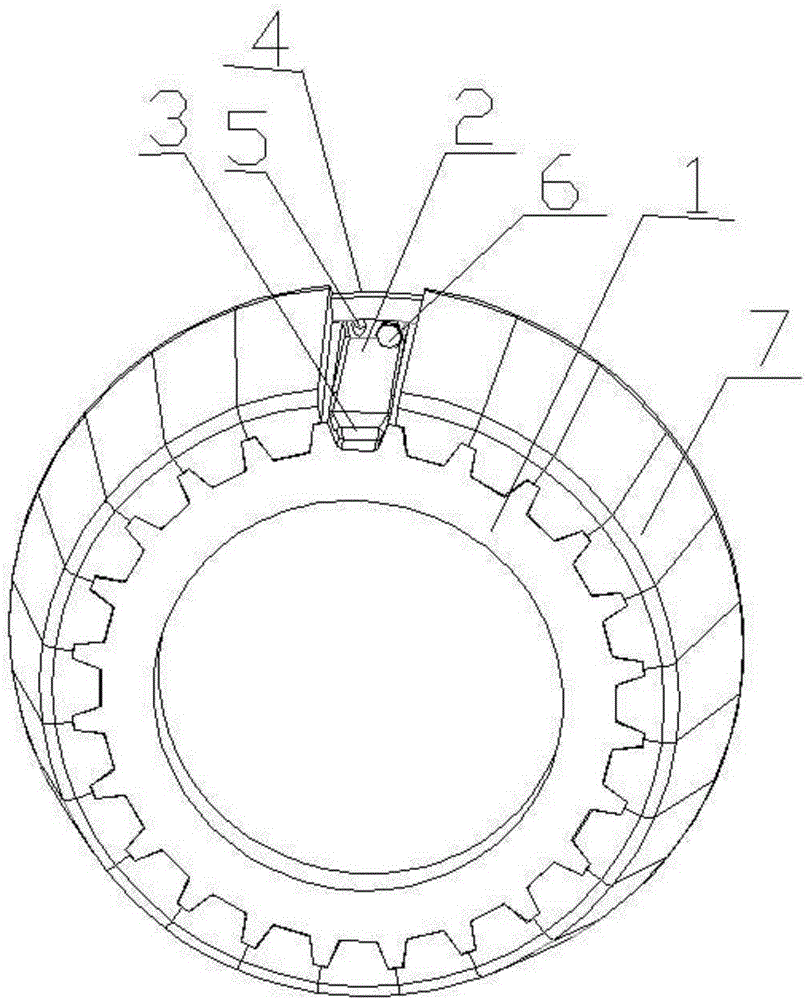
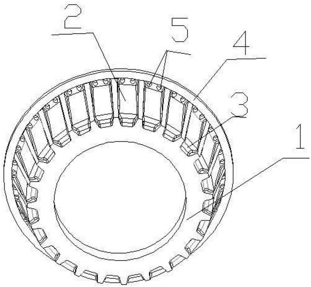
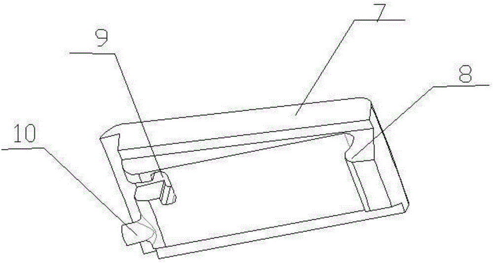
[0020] Example 1, as Figure 1-3 Shown: the combined vertical wear-resistant roller of the present invention consists of a grinding roller body 1, a through groove 2, a hook groove 3, an annular baffle 4, a positioning through hole 5, a bolt 6, a fan-shaped wear-resistant block 7, a hook 8, and a bolt clamp Slot 9, limit post 10 and other components.

[0021] The grinding roller body 1 is tapered, and this type of grinding roller is in the prior art, and its structure will not be described in detail. The grinding roll body 1 is made of cast iron or cast steel. Preferably: the grinding roll body 1 is made of ductile iron or graphite steel.

[0022] A plurality of axially extending through grooves 2 are distributed on the outer circumferential surface of the grinding roller body 1 . A hook groove 3 is provided in the through groove 2 near the small mouth end of the grinding roller body 1 , and the opening of the groove of the hook groove 3 faces the grinding roller body 1 . T...


PUM


Abstract

The invention discloses a combined vertical wear-resistant roller which comprises a conical grinding roller body. A plurality of through grooves extending in the axial direction are distributed in the outer circumference face of the grinding roller body. Hook grooves are formed in positions, close to the small end of the grinding roller body, in the through grooves. An annular baffle is arranged at the large-opening end of the outer circumference face of the grinding roller body. Two positioning through holes corresponding to each through groove are formed in the annular baffle, wherein a bolt is inserted in one positioning through hole, and the head of the bolt is located in the corresponding through groove. A plurality of sector wear-resistant blocks are distributed on the outer circumference face of the grinding roller body. The lower surfaces of the small ends of the sector wear-resistant blocks are provided with hooks which extend downwards and are matched with the hook grooves. The large ends of the sector wear-resistant blocks are provided with limited posts and bolt clamping grooves. The hooks of the sector wear-resistant blocks are hooked in the hook grooves. The limited posts of the sector wear-resistant blocks are inserted in the positioning through holes. The heads of the bolts stretch in the bolt clamping grooves and are locked through nuts. The machining difficulty of the wear-resistant blocks is lowered, the yield is increased, and cost is reduced.

Description

technical field [0001] The invention relates to a vertical conical wear-resistant roller, in particular to a combined vertical wear-resistant roller. Background technique [0002] The rapid development of modern industry has made equipment have higher requirements on the wear resistance of components, such as grinding rollers, grinding discs and crusher hammers of vertical mills used in cement, mining, metallurgy, power plants or various similar industries. Etc., the hardness and toughness of traditional steel materials are usually contradictory. The existing technology mostly uses bimetal composite and ceramic metal composite technology to improve the wear resistance of the material. After the main wear parts of such products are completely consumed, the ductile metal parts are due to The wear resistance is low and the use value is reduced, but it cannot be disassembled because it is connected with the wear-resistant parts by metallurgical bonding, and it is usually treated...

Claims


Application Information

Patent Timeline
IPC IPC(8): B02C15/00
Inventor 牟元全侯占东温放放欧成忠张秀军贾世敏黄东风
Owner CHONGQING LUOMAN NEW MATERIAL TECH CO LTD
Why Eureka
Try Eureka