
Heat pump device and air conditioner having same, heat pump water heater, refrigerator and refrigerating machine

A technology of heat pump devices and inverters, which is applied to compressors with reversible cycles, refrigerators, and compressors with irreversible cycles, etc., which can solve the problems of decreased power detection accuracy, unrelated timing current cycles, and inability to maintain constant electric energy. , to achieve the effect of preventing stagnation inside the compressor

Active Publication Date: 2017-05-24
MITSUBISHI ELECTRIC CORP
View PDF7 Cites 0 Cited by
  • Summary
  • Abstract
  • Description
  • Claims
  • Application Information

AI Technical Summary

Problems solved by technology

[0010] However, in the technique described in Patent Document 4, there is a problem that since the sampling period is equally divided into a plurality, there is no relationship between the timing of current detection and the current period, and if the detection timing deviates from the current period, the The accuracy of power detection decreases, and the power supplied to the compressor motor may not be kept constant

Method used


Image

  • Heat pump device and air conditioner having same, heat pump water heater, refrigerator and refrigerating machine
  • Heat pump device and air conditioner having same, heat pump water heater, refrigerator and refrigerating machine
  • Heat pump device and air conditioner having same, heat pump water heater, refrigerator and refrigerating machine

Examples


Embodiment approach 1

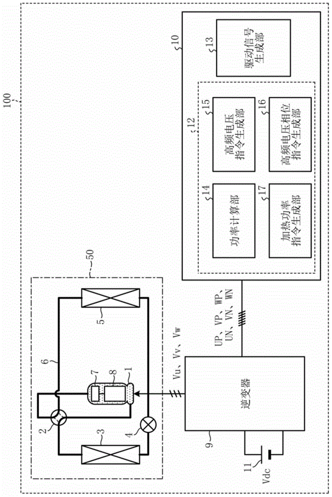
[0083] figure 1 It is a figure which shows one structural example of the heat pump apparatus concerning Embodiment 1. Such as figure 1 As shown, in the heat pump device 100 according to Embodiment 1, the compressor 1 , the four-way valve 2 , the heat exchanger 3 , the expansion mechanism 4 , and the heat exchanger 5 are sequentially connected through the refrigerant piping 6 to form a refrigeration cycle 50 . In addition, in figure 1 In the illustrated example, the basic structure forming the refrigeration cycle 50 is shown, but some structural elements are omitted from the figure.

[0084] Inside the compressor 1 are provided a compression mechanism 7 for compressing refrigerant and a compressor motor 8 for operating the compression mechanism 7 . The compressor motor 8 is a three-phase motor having three-phase motor windings of U-phase, V-phase, and W-phase.

[0085] The compressor motor 8 is electrically connected to the inverter 9 . The inverter 9 is connected to a DC ...

Embodiment approach 2

[0188] In this embodiment, an air conditioner, a heat pump water heater, a refrigerator, and a refrigerator to which the heat pump device described in Embodiment 1 can be applied will be described.

[0189] Here, refer to Figure 21 , Figure 22 A more specific configuration of the refrigeration cycle of the air conditioner, heat pump water heater, refrigerator, and refrigerator according to the second embodiment and the operation in the normal operation mode will be described.

[0190] Figure 21 It is a figure which shows one structural example of the refrigeration cycle concerning Embodiment 2. also, Figure 22 yes means Figure 21 A Mollier diagram of the state transitions of the refrigerant in the refrigeration cycle is shown. exist Figure 22 , the horizontal axis represents the specific enthalpy h, and the vertical axis represents the refrigerant pressure P.

[0191] The refrigeration cycle 50a according to Embodiment 2 has a main refrigerant circuit 58 that circ...


PUM


Abstract

The present invention provides a heat pump device and an air conditioner, a heat pump water heater, a refrigerator and a refrigerating machine with the same, which can keep the electric energy supplied to the compressor motor constant when the compressor motor is limited to be energized, so that the compressor motor The amount of heating is kept constant, thereby efficiently and reliably preventing liquid refrigerant from stagnating inside the compressor. This heat pump device adopts a structure in which a high-frequency voltage synchronized with a carrier signal is supplied to the compressor motor during the operation standby period of the compressor to limit the energization of the compressor motor. Voltage, voltage of each phase, or current of each phase, each detection value corresponding to one cycle of the high-frequency energization cycle is restored, and the control is performed so that the restored detection values ​​corresponding to one cycle of the high-frequency energization cycle are used The calculated power value is consistent with the heating power command required to discharge the liquid refrigerant trapped inside the compressor to the outside of the compressor.

Description

technical field [0001] The present invention relates to a heat pump device and an air conditioner, a heat pump water heater, a refrigerator and a refrigerating machine having the same. Background technique [0002] Conventionally, as a technique for preventing liquid refrigerant from accumulating inside the compressor during the stoppage of the heat pump device used in an air conditioner, there is energization of the motor winding (hereinafter referred to as "limited energization") so as not to drive the motor of the compressor. ) to heat the compressor so that the liquid refrigerant is vaporized and discharged. For example, it is disclosed that when the compressor is on standby, an AC voltage of about 20 kHz higher than the normal frequency during normal operation is supplied to the compressor motor, thereby utilizing the switching loss caused by the switching elements constituting the inverter. The heat generated by the motor and the heat generated by the motor prevent th...

Claims


Application Information

Patent Timeline
Patent Type & Authority Patents(China)
IPC IPC(8): F25B1/00F24F11/02H02M7/48
CPCH02M7/5395F25B1/10F25B13/00F25B40/00F25B2313/003F25B2400/13F25B2600/021Y02B30/70F25B41/39F24F11/89F25B1/00F25B49/025
Inventor 畠山和德神谷庄太汤浅健太松下真也楠部真作
Owner MITSUBISHI ELECTRIC CORP
Learn More