


Quick Research
Generate reliable direction feasibility study reports for your R&D in just a few steps.

Technical Q&A
Discover and master advanced knowledge NOW. Basics, ideas, possibilities, all at once.

Find Solutions
As an expert in R&D theories, this can generate solutions to your technical problems instantly.

Evaluate Feasibility
Analyze your overall solution with one click, know your potential R&D risks in advance.

Monitor Landscape
Get weekly tech updates, stay abreast of the latest tech innovations and key insights.
Rotary socket
A socket and plug-in technology, applied in the direction of flexible/rotatable wire connectors, electrical components, coupling devices, etc., can solve the problems that cannot meet the needs of use and cannot be adjusted according to needs, and achieves a simple structure, easy to use, and operation. handy effect
- Summary
- Abstract
- Description
- Claims
- Application Information
AI Technical Summary
Problems solved by technology
Method used
Image

Examples
Embodiment Construction
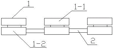
[0009] Such as figure 1 It is a schematic diagram of the structure of the present invention, a rotary socket, including several boards 1 and board connectors 2, the board 1 is circular, and the board 1 is divided into an upper jack 1-1 and a lower base 1-2, the lower part The bases 1-2 are connected through board connectors 2 .
[0010] When in use, the rotation of the upper socket 1-1 can be realized by rotating the lower base 1-2, the structure is flexible and changeable, the space occupied is small, and it is convenient and practical.
[0011] The above description is only illustrative of the present invention, rather than restrictive. Those of ordinary skill in the art understand that many modifications, changes or the like can be made without departing from the spirit and scope defined by the appended claims. effect, but all will fall within the protection scope of the present invention.
PUM
 Abstract
Description
Claims
Application Information
 - R&D Engineer
- R&D Manager
- IP Professional
- Industry Leading Data Capabilities
- Powerful AI technology
- Patent DNA Extraction
Browse by: Latest US Patents, China's latest patents, Technical Efficacy Thesaurus, Application Domain, Technology Topic, Popular Technical Reports.
© 2024 PatSnap. All rights reserved.Legal|Privacy policy|Modern Slavery Act Transparency Statement|Sitemap|About US| Contact US: help@patsnap.com