Eureka AIR delivers breakthrough ideas for toughest innovation challenges, trusted by R&D personnel around the world.

Novel common-rail fuel injector

A technology of common rail injectors and injectors, which is applied in the direction of machines/engines, fuel injection devices, engine components, etc., can solve the problems of low product qualification rate, restrictions on the promotion and application of common rail systems, and complex tolerance detection and manufacturing Cost and other issues

Active Publication Date: 2015-12-30
NANYUE FUEL INJECTION SYST CO LTD
View PDF7 Cites 5 Cited by
  • Summary
  • Abstract
  • Description
  • Claims
  • Application Information

AI Technical Summary

Problems solved by technology

The disadvantage of the typical Bosch common rail injector construction described above is that the tolerance range necessary for the good operation of the injector can only be achieved by very complicated testing and expensive manufacturing costs, especially when depending on the injection pressure in the pressure control chamber. When adjusting the diameter ratio between the inlet orifice and the outlet orifice due to the oiler cracking pressure
[0004] At present, the technological level and mechanical processing equipment of general fuel system manufacturers in my country cannot fully meet the requirements, and the product qualification rate is low, which restricts the promotion and application of the common rail system to a certain extent.

Method used


Image

  • Novel common-rail fuel injector
  • Novel common-rail fuel injector
  • Novel common-rail fuel injector

Examples


Embodiment Construction

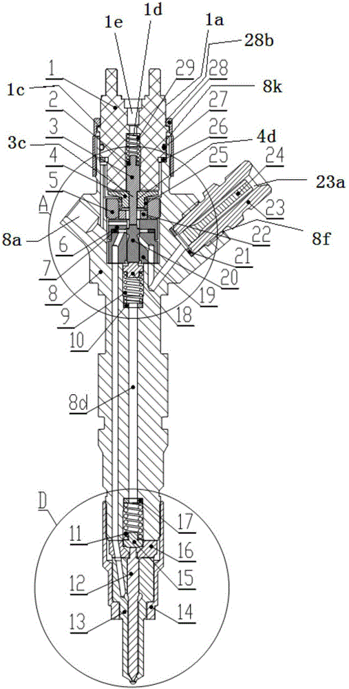
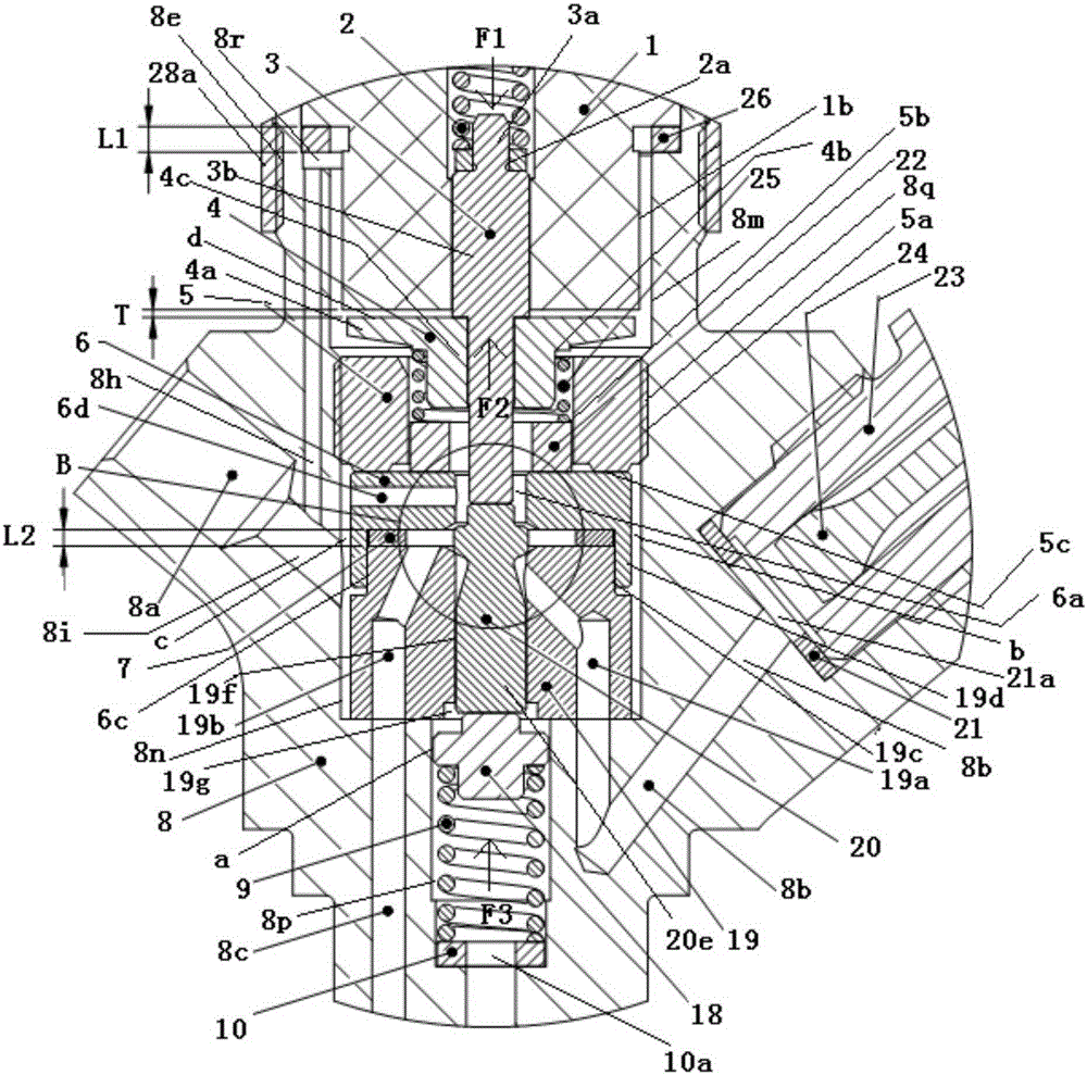
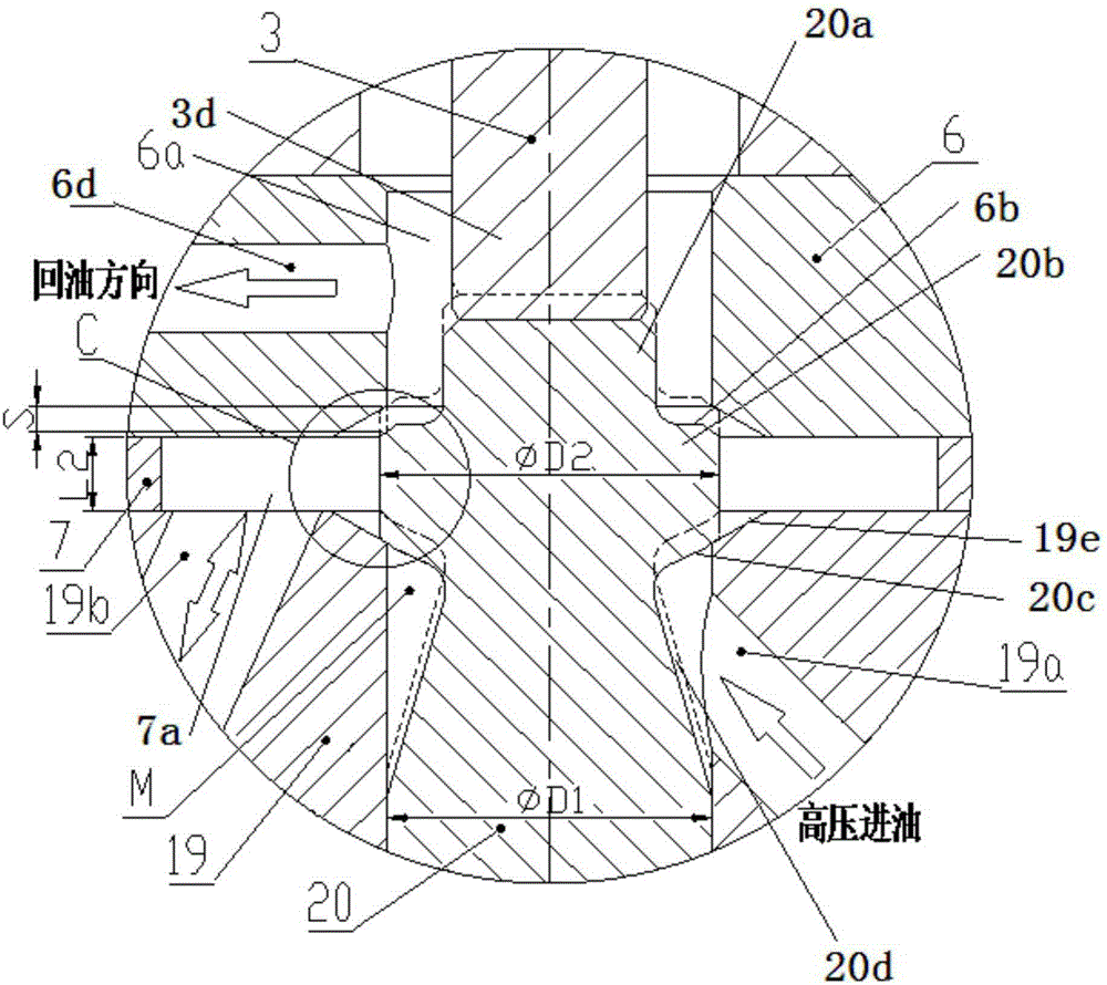
[0055] see Figure 1 to Figure 7 , a new type of common rail injector shown in the figure is assembled from injector parts, solenoid valve parts and fuel injector parts. The specific structure is as follows:

[0056] The fuel injector body components include fuel injector body 8, sealing gasket 21, fuel inlet pipe joint 23, and slot filter element 24. The fuel injector body 8 is provided with an upper external thread 8e, an oil return pipe joint installation hole 8a, and an oil inlet pipe joint. The installation hole 8f and the lower external thread 8g, the upper and lower external threads 8e, 8g are respectively arranged on the upper and lower ends of the outer edge of the injector body 8, and the oil return pipe joint installation hole 8a and the oil inlet pipe joint installation hole 8f are arranged on the injector Upper middle position of the body.

[0057] In the injector body, there are installation holes for solenoid valve components, oil inlet passage 8b, first oil re...


PUM


Abstract

The invention discloses a novel common-rail fuel injector. The common-rail fuel injector comprises a fuel injector body component, an electromagnetic valve component and a fuel injection nozzle component, wherein the electromagnetic valve component and the fuel injection nozzle component are mounted at upper and lower ends of the fuel injector body component respectively. The fuel injection control function is realized in such a manner that the two-position three-way electromagnetic control valve component and the fuel injection nozzle component with adjustable opening pressure are combined, the fuel injector is simpler in structure, and the initial fuel injection point and the fuel injection quantity can be controlled flexibly. An electromagnetic control valve core of the fuel injector is designed to adopt a fuel pressure self-balancing structure, the fuel injection starting response speed can be significantly increased, the driving current of an electromagnet can be significantly reduced, the service life of the electromagnet is effectively prolonged, and the reliability of the electromagnet is effectively improved. The common-rail fuel injector is free of pressure control chamber structures, outgoing fuel throttling hole control ball valves and control piston couple pairs of other traditional common-rail fuel injectors, so that precise parts and components with great machining technology difficulty are not required, the machining difficulty is greatly reduced, and the technological cost is correspondingly reduced.

Description

technical field [0001] The invention relates to a fuel injector suitable for a common rail system of a diesel engine, in particular to a novel common rail fuel injector capable of flexibly controlling the fuel injection starting point and the fuel injection quantity. Background technique [0002] At present, the common rail fuel injectors widely used at home and abroad are mainly composed of solenoid valves, pressure amplification systems and fuel injection nozzle parts. Among them, the pressure amplification system is mainly composed of a pressure control chamber, a control piston pair, an oil outlet orifice control ball valve, and a needle valve body oil tank. Among them, the pressure control chamber is mainly composed of the top of the control piston, the oil inlet orifice, and the oil outlet orifice. The volume of the pressure control chamber determines the response speed when the needle valve is opened and closed. The flow characteristics and consistency of the oil in...

Claims


Application Information

Patent Timeline
IPC IPC(8): F02M51/06F02M61/10F02M61/16
Inventor 龙美彪欧阳玲湘黄民备刘成谭四喜
Owner NANYUE FUEL INJECTION SYST CO LTD
Why Eureka
Eureka Blog
Learn More