
A Hybrid Excitation Permanent Magnet Linear Generator with Double Windings on the Yoke

A technology of mixed excitation and permanent magnet straight line, which is applied to the shape/style/structure of winding conductors, the static parts of magnetic circuit, the shape/style/structure of magnetic circuit, etc., which can solve the problems of high manufacturing cost, long winding ends and copper Large quantities and other issues, to achieve high material utilization, reduce magnetic resistance, and low cost

Active Publication Date: 2018-03-30
SHANDONG UNIV
View PDF6 Cites 0 Cited by
  • Summary
  • Abstract
  • Description
  • Claims
  • Application Information

AI Technical Summary

Problems solved by technology

[0009] In addition, the existing permanent magnet motors mostly use distributed windings or concentrated windings spanning multiple pole pitches, which generally have long winding ends, a large amount of copper, high manufacturing costs, high copper consumption during motor operation, and low efficiency. Disadvantages, especially for motors with large iron core lengths, this disadvantage is particularly prominent, it is necessary to use a special winding coil connection method to reduce the winding end, reduce the use of copper, and improve the operating efficiency of the motor

Method used


Image

  • A Hybrid Excitation Permanent Magnet Linear Generator with Double Windings on the Yoke
  • A Hybrid Excitation Permanent Magnet Linear Generator with Double Windings on the Yoke
  • A Hybrid Excitation Permanent Magnet Linear Generator with Double Windings on the Yoke

Examples


Embodiment 1

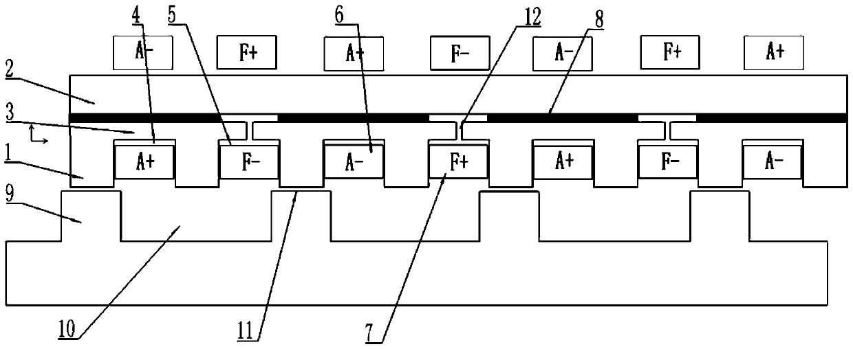
[0066] Such as image 3 As shown, the number of stator teeth of the motor is 8, the number of mover teeth is 4, and the number of permanent magnet blocks is 4. This embodiment includes a stator, a mover, a main air gap and an additional air gap, and the stator includes a stator core, a permanent magnet and a stator slot , the stator core includes stator teeth 1, stator back yoke 2 and stator slot yoke 3, the stator core is made of ferromagnetic material with high magnetic permeability, the stator core is provided with stator slots, the stator slot includes armature slot 4 and excitation Slot 5, armature slot 4 and excitation slot 5 are alternately arranged at intervals, excitation winding 7 is placed in excitation slot 5, armature winding 6 is placed in armature slot 4, and the winding penetrates from one excitation slot or armature slot, and then Passing out along the outside of the stator back yoke in the outward direction to form a coil, the motor winding is wound around th...

Embodiment 2

[0068] Such as Figure 4 As shown, the number of stator teeth of the motor is 8, the number of teeth of the mover is 4, and the number of permanent magnet blocks is 8. This embodiment includes a stator, a mover, a main air gap and an additional air gap, and the stator includes a stator core, permanent magnets and stator slots , the stator core includes stator teeth 1, stator back yoke 2 and stator slot yoke 3, the stator core is made of ferromagnetic material with high magnetic permeability, the stator core is provided with stator slots, the stator slot includes armature slot 4 and excitation Slot 5, armature slot 4 and excitation slot 5 are alternately arranged at intervals, excitation winding 7 is placed in excitation slot 5, armature winding 6 is placed in armature slot 4, and the winding penetrates from one excitation slot 5 or armature slot 4 , and then go out along the outer side of the stator back yoke to form a coil, the motor winding is wound around the stator slot yo...


PUM


Abstract

The invention discloses a hybrid excitation permanent magnet linear generator with dual windings on the yoke. The stator slots include armature slots and excitation slots. The armature slots and excitation slots are alternately arranged at intervals. A set of Armature winding, a set of excitation winding is provided in the excitation slot; a main air gap is provided between the stator teeth and the mover teeth, the slot yoke of the excitation slot is disconnected, and an additional air gap is provided; the armature The winding is fed with alternating current, and the field winding is passed with a constant direction of direct current. The interaction between the armature current magnetic field, the field current magnetic field and the magnetic field generated by the permanent magnet makes the magnetic flux on the stator teeth change each other, using the reluctance between the stator and the mover The changes create torque and generate electricity. The invention effectively reduces the number of power switching devices, reduces the possibility of failure of the power switching devices in the motor control circuit, and improves reliability.

Description

technical field [0001] The invention relates to a hybrid excitation permanent magnet linear generator with double windings on the yoke. Background technique [0002] The linear motor drive device can directly convert the input electric energy into linear kinetic energy on the required occasion, realize linear motion, save the mechanical transmission conversion device in the traditional rotation-linear conversion drive mode, and greatly reduce the volume of the transmission device. It improves the reliability and efficiency of the whole system, and effectively reduces the cost and maintenance cost of the equipment. Not only that, but also the high speed, high precision and robustness that the traditional rotary-linear conversion drive method cannot achieve. In addition, the transmission conversion device will significantly increase the vibration and noise of the transmission system, reducing the control accuracy and performance of the system. Therefore, in the modern industr...

Claims


Application Information

Patent Timeline
Patent Type & Authority Patents(China)
IPC IPC(8): H02K3/28H02K1/17H02K1/16H02K1/34
Inventor 王道涵
Owner SHANDONG UNIV
Learn More