Pressure sensing-based touch panel and display device, and pressure sensing implementation method
A touch screen and pressure technology, applied in the field of pressure sensing, display devices, and pressure sensing-based touch screens, can solve problems such as screen pressure imbalance, screen touch damage, and multi-touch prone to erroneous operations. Achieve the effect of reducing the loss of light energy and avoiding the weakening of LCD light perception
- Summary
- Abstract
- Description
- Claims
- Application Information
AI Technical Summary
Problems solved by technology
Method used
Image
Examples
Embodiment 1
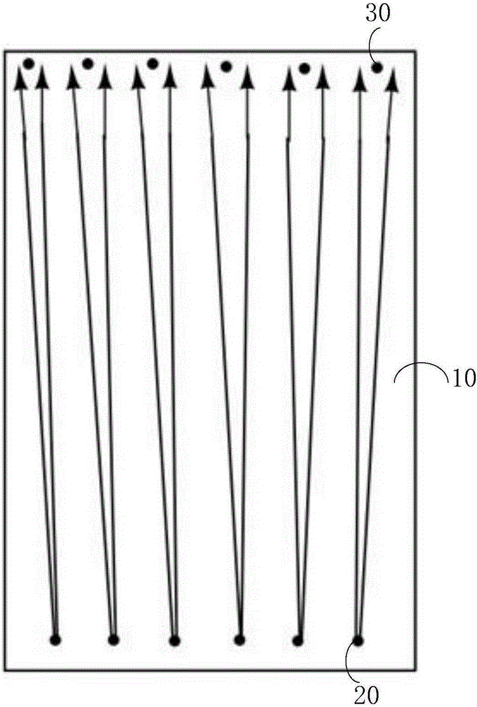
[0067] This embodiment provides a touch screen based on pressure sensing, the touch screen includes a touch screen, one or more pairs of infrared light emitters and infrared light receivers arranged under the touch screen, wherein the touch screen The control screen is deformed and bent by pressing, and the infrared light emitted by any of the infrared light emitters is received by the corresponding infrared light receiver after being totally reflected by the touch screen, and the infrared light emitter is directed toward the An angle θ is formed between the infrared light emitted by the touch screen and a vertical line perpendicular to the touch screen.
Embodiment 2
[0069] This embodiment provides a touch screen based on pressure sensing, combined with figure 1 and figure 2 As shown, the touch screen includes a touch screen 10 that can be deformed and bent by pressing, six pairs of infrared light emitters 20 and infrared light receivers 30 arranged under the touch screen 10 .
[0070] Such as image 3 As shown, the touch screen 10 includes a glass cover plate 11, an ITO electrode material 12 arranged under the glass cover plate 11 (the ITO electrode material is a touch electrode material) and an infrared cut filter film arranged under the ITO electrode material 12 13 , the edge ink 14 is arranged between the ITO electrode material 12 and the infrared cut filter film 13 , and the edge ink 14 is arranged along the edge of the touch screen 10 . Among them, the function of the infrared cut-off filter film is to make the infrared light totally reflect and the visible light fully transmit. The side of the glass cover plate 11 in contact wit...
Embodiment 3
[0086] This embodiment provides a display device based on pressure sensing, such as Figure 6 , Figure 7 As shown, the display device includes a touch screen 10 and an LCD 40 arranged below the touch screen 10. Six pairs of infrared light emitters 20, infrared light receivers 30 and two groups of reflective sheets are arranged below the LCD. These two groups of reflective sheets The sheets are respectively a first group of reflective sheets 51 arranged near the infrared light emitter 20 and a second group of reflective sheets 52 arranged near the infrared light receiver 30 .
[0087] Such as Figure 8 As shown, the touch screen 10 includes a glass cover plate 11, an ITO electrode material 12 arranged under the glass cover plate 11 (the ITO electrode material is a touch electrode material) and an infrared cut filter film arranged under the ITO electrode material 12 13 , the edge ink 14 is arranged between the ITO electrode material 12 and the infrared cut filter film 13 , an...
PUM
 Abstract
Description
Claims
Application Information
 - R&D
- Intellectual Property
- Life Sciences
- Materials
- Tech Scout
- Unparalleled Data Quality
- Higher Quality Content
- 60% Fewer Hallucinations
Browse by: Latest US Patents, China's latest patents, Technical Efficacy Thesaurus, Application Domain, Technology Topic, Popular Technical Reports.
© 2025 PatSnap. All rights reserved.Legal|Privacy policy|Modern Slavery Act Transparency Statement|Sitemap|About US| Contact US: help@patsnap.com


