
Multi-stage perforation redundant ignition control device

A technology of ignition control and ignition device, which is applied in wellbore/well components, production fluids, earth-moving drilling, etc., can solve the problems of ignition failure, high rework cost, complicated circuit design, etc., and avoid accidental well closure and ignition. Easy to operate and ensure smooth effect

Active Publication Date: 2019-03-22
CHINA PETROCHEMICAL CORP +3
View PDF7 Cites 0 Cited by
  • Summary
  • Abstract
  • Description
  • Claims
  • Application Information

AI Technical Summary

Problems solved by technology

The two methods have their own advantages and disadvantages: the mechanical structure of the voltage control type is more complicated, the circuit design is simple, and the ignition operation is convenient; the electronic type has a simple mechanical structure and more complicated circuit design, and generally requires a special ignition panel and program, which can be monitored and recorded in real time. ignition process
However, due to the insufficient design margin of the ignition control method, ignition failures often occur, resulting in high rework costs and complicated follow-up processing operations

Method used


Image

  • Multi-stage perforation redundant ignition control device
  • Multi-stage perforation redundant ignition control device

Examples


Embodiment Construction

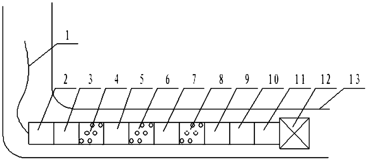
[0011] In the present invention, a plurality of perforating guns for shooting out formations and corresponding multi-stage ignition devices for circuit control are sequentially connected in series between the depth calibration instrument 2 and the setting tool 11 in the operating horizontal wellbore 13. The gun head at the lower end of the depth calibration instrument leads to two parallel lines, one line is connected to the voltage control switch, and the other line is used to connect to the electric selection switch; each voltage control switch is connected with a diode; each voltage control switch is connected in series until the bridge plug igniter is connected , each electric selection switch is connected in series, the top is connected with a resistor, and each diode is connected in series until it is connected to a single-core cable 1; each voltage-controlled switch and each electric selection switch is connected with an electric detonator, and the electric detonator is c...


PUM


Abstract

The invention relates to a multistage perforating redundancy ignition control device. Two circuits are led out from the lower end of a depth checking apparatus; one of the two circuits is connected with voltage controlling switches while the other circuit is connected with electric separation switches; each pressure control switch is connected with a diode, and is serially connected to a bridge plug igniter; the electric separation switches are serially connected to one another; the top of each electric separation switch is connected with a resistor; each voltage controlling switch and the corresponding electric separation switch are connected with an electric detonator; and each electric detonator is connected with the corresponding voltage controlling switch via the corresponding diode. Two electric detonators which are controlled by the corresponding voltage controlling switch, the corresponding electric separation switch or the corresponding diode are arranged in each perforating gun. In a first-stage perforating gun, the corresponding voltage controlling switch triggers the corresponding electric detonators, or the circuit of the corresponding diode triggers the other electric detonator. In a second-stage perforating gun and a third-stage perforating gun, the corresponding voltage controlling switches trigger the electric detonators, or electronic switches trigger the other electric detonators. Voltage control and electronic multi-ignition technologies are adopted, ignition operation is facilitated, reliability of perforating operation is improved, and the multistage perforating redundancy ignition control device is suitable for shale gas exploitation perforating operation.

Description

technical field [0001] The invention relates to the technical field of cable transmission perforation for oil and gas wells, in particular to a redundant ignition control device for multi-stage perforation. Background technique [0002] In the development of shale gas, due to the completion conditions of horizontal wells and the needs of fracturing formations, perforation operations often use the technology of multi-stage perforation bridge plugs combined with horizontal well cable pumping. This process requires cable pumping in horizontal wells. After the pipe string is transported to the target layer, the bridge plug gunpowder is ignited by electricity, and the bridge plug is set to form a temporary blockage. The detonator realizes the perforation of the first perforating gun, and then lifts it up to the next position, energizes and detonates the second power generation detonator, realizes the perforation of the second perforating gun, and so on. [0003] At present, the ...

Claims


Application Information

Patent Timeline
Patent Type & Authority Patents(China)
IPC IPC(8): E21B43/1185
Inventor 廖勇潘金国曹红海魏大农田海涛饶海涛周璐陈志蓉
Owner CHINA PETROCHEMICAL CORP
Learn More