
sludge storage tank

A technology for storage tanks and sludge, which is applied in the directions of transportation, packaging, loading/unloading, etc., can solve the problems of sludge storage tanks losing mud-scraping performance and maintenance difficulties, achieving obvious energy-saving effects, good sludge discharge effects, and preventing sludge The effect of accumulation of mud

Active Publication Date: 2017-05-03
HUNAN JIUFANG ENVIRONMENTAL PROTECTION MACHINERY
View PDF10 Cites 0 Cited by
  • Summary
  • Abstract
  • Description
  • Claims
  • Application Information

AI Technical Summary

Problems solved by technology

[0003] The purpose of the present invention is to provide a sludge storage tank to solve the problems that the sludge storage tank loses the mud scraping performance and is difficult to maintain

Method used


Image

  • sludge storage tank
  • sludge storage tank
  • sludge storage tank

Examples


Embodiment Construction

[0026] The embodiments of the present invention will be described in detail below with reference to the accompanying drawings, but the present invention can be implemented in various ways defined and covered by the claims.

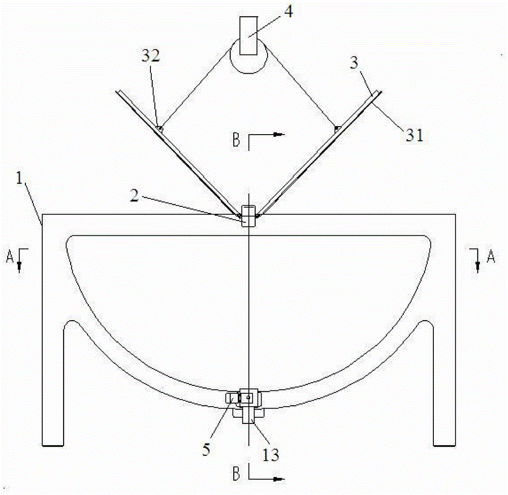
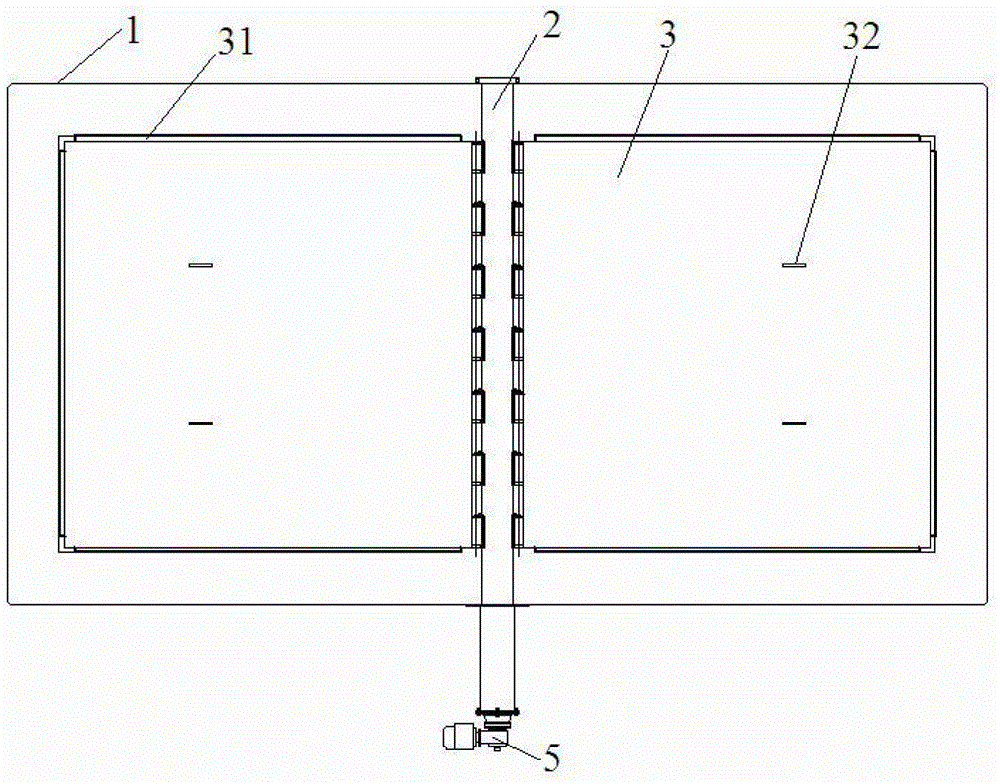
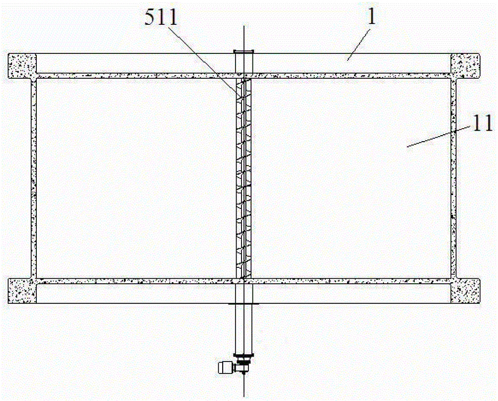
[0027] see Figure 1 ~ Figure 3 The sludge storage tank includes a tank body 1, a beam 2, a tank cover 3, a lifting device 4, and a sludge discharge device 5. The bottom surface of the tank body 1 is a horizontal cylindrical surface, and the sides of the tank body 1 are located at both axial ends of the tank body. And the sides of the axial ends of the pool body are planes, the top of the pool body 1 is provided with a feed port 11 along the horizontal axial section, the beam 2 is fixed on the feed port 11 at the top of the pool body 1 along the axial direction, and the beam 2 is movable and hinged There is a pool cover 3, the edge of the pool cover 3 is attached to the inner wall of the pool body 1, a lifting device 4 for lifting and opening and closing t...


PUM


Abstract

A sludge storage pool comprises a pool body, a cross beam, a pool cover, a hoisting device and a sludge discharging device. The bottom face of the pool body is a cylinder face in the horizontal direction. The side faces of the pool body are located at the two axial ends of the pool body. A feeding port is formed in the section of the top of the pool body in the horizontal axial direction. The cross beam is fixed to the feeding port in the top of the pool body in the axial direction. The pool cover is movably hinged to the cross beam. The edge of the pool cover is attached to the inner wall of the pool body. The hoisting device used for hoisting, opening and closing the pool cover is arranged above the feeding port of the pool body. A groove is formed in the inner bottom face of the pool body in the axial direction and internally provided with the slurry discharging device emptying sludge in the pool body. The sludge discharging device comprises a spiral conveyor axially fixed to the inner bottom face of the pool body, and a sludge discharging pipeline communicated with the spiral conveyor is arranged outside the pool body. The pool cover is overturned through gravity without external force, the energy saving effect is obvious, sealing strips are arranged on the edge of the pool cover, and sludge scraping can be achieved during sealing. The spiral conveyor is matched, and sludge accumulation is effectively prevented.

Description

technical field [0001] The invention relates to sewage treatment equipment, in particular to a sludge storage tank for storing buffered and dehydrated sludge. Background technique [0002] In the treatment of urban sludge, it is necessary to store and buffer the dehydrated sludge of the sewage treatment plant to facilitate the adjustment and stability of the sludge treatment system; due to the poor fluidity and stickiness of the sludge, it will produce stench and pollute the environment if it is exposed to the environment. It is not easy to discharge into the container, and complex mechanical devices are required to push it out and scrape it clean. Most of the existing sludge storage tanks use a cylindrical cylinder. The bottom of the cylinder is equipped with a sliding frame device, and an oil cylinder and an oil pressure system are installed outside. In the sludge, the sludge environment can easily cause the carriage to rust and cause the oil cylinder to fail to push the ...

Claims


Application Information

Patent Timeline
Patent Type & Authority Patents(China)
IPC IPC(8): B65G65/46B65G69/00
Inventor 易庆国朱志恒罗志诚胡笋
Owner HUNAN JIUFANG ENVIRONMENTAL PROTECTION MACHINERY
Learn More