
Sponge cutting machine

A technology of sponge cutting machine and suction fan, which is applied in metal processing and other directions, can solve the problems of high cutting defective rate, waste of material processing links, large waste chips, etc., and achieve the effect of avoiding circular cutting and improving work efficiency

Inactive Publication Date: 2015-12-23
CHENGDU DUOLIDUO NEW MATERIAL
View PDF7 Cites 3 Cited by
  • Summary
  • Abstract
  • Description
  • Claims
  • Application Information

AI Technical Summary

Problems solved by technology

[0002] When the sponge cutting machine is cutting the sponge, it is easy to generate a large amount of waste. If the waste is not disposed of in time, it will affect the damage to the cutting motor, and also affect the cutting quality of the sponge, resulting in a high rate of defective products. , the material processing link causes waste
At the same time, it is difficult for the existing cutting machine to cut the curve of the sponge, which requires manual labor to complete the circular cutting, thereby increasing the labor force.

Method used


Image

  • Sponge cutting machine
  • Sponge cutting machine

Examples


Embodiment Construction

[0014] The present invention will be described in further detail below through specific implementation examples and in conjunction with the accompanying drawings.

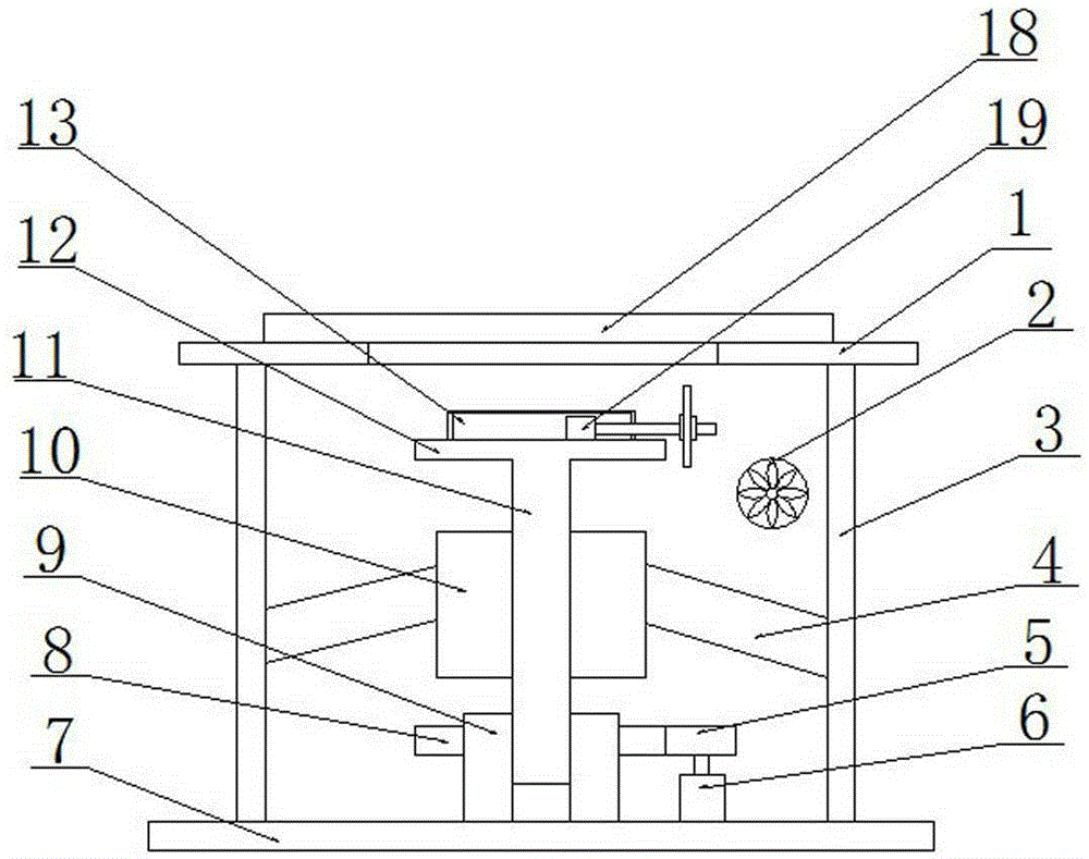
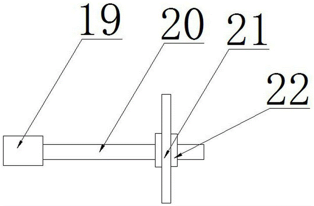
[0015] Figure 1-2 Shown is a sponge cutting machine provided by the present invention, including: workbench 1, suction fan 2, housing 3, bracket 4, driving gear 5, rotating motor 6, bottom plate 7, driven gear 8, rotating cylinder 9 , guide sleeve 10, rotating rod 11, disc 12, support shell 13, sponge 18, cutting motor 19 cutting motor output shaft 20, nut 22 and cutting piece 21. The housing 3 is provided with a workbench 1, and a circular through groove is provided on the workbench 1; the housing 3 is provided with a rotating cylinder 9, and the lower end of the rotating cylinder 9 is rotatably connected with the bottom plate 7 of the housing; The outer circular surface of the rotating cylinder 9 is provided with a driven gear 8, the driven gear 8 is provided with a driving gear 5 cooperating with it, and the d...


PUM


Abstract

The invention discloses a sponge cutting machine which comprises a shell. A workbench is arranged on the shell. A circular through groove is formed in the workbench. A rotating cylinder is arranged inside the shell. The lower end of the rotating cylinder is rotatably connected with a bottom plate of the shell. A driven gear is arranged on the outer circular surface of the rotating cylinder. The driven gear is provided with a driving gear matched with the driven gear. The driving gear is provided with a rotating motor. A rotating rod in thread fit with the rotating cylinder is arranged inside the rotating cylinder. A disc is fixedly connected to the upper end of the rotating rod. A supporting shell and a cutting motor inside the supporting shell are arranged on the disc. A rectangular groove is formed in an output shaft of the cutting motor in the axial direction. By means of the sponge cutting machine, the working efficiency can be improved.

Description

technical field [0001] The invention relates to the technical field of cutting machines, in particular to a sponge cutting machine. Background technique [0002] When the sponge cutting machine is cutting the sponge, it is easy to generate a large amount of waste chips. If the waste chips are not processed in time, it will affect the damage to the cutting motor, and also affect the cutting quality of the sponge, resulting in a high rate of defective products. , The material processing link has caused waste. Simultaneously existing cutting machine is difficult to carry out curve cutting to sponge, and causes need manually to complete circular cutting, thereby has increased artificial labor force. Contents of the invention [0003] The object of the present invention is to provide a kind of sponge cutting machine, to solve the deficiencies in the prior art. [0004] For realizing the object of the present invention, the technical scheme that adopts is: [0005] A sponge c...

Claims


Application Information

Patent Timeline
Patent Type & Authority Applications(China)
IPC IPC(8): B26D1/12B26D7/26B26D7/01B26D7/18
Inventor 刘华昆
Owner CHENGDU DUOLIDUO NEW MATERIAL
Learn More