
Device and method used for SDH (Synchronous Digital Hierarchy) clock jitter test

A clock jitter and clock recovery technology, applied in multiplex communication, time division multiplexing systems, electrical components, etc., can solve the problem of inaccurate measurement of clock jitter signal amplitude and frequency, and increase the cost of SDH clock jitter measurement. , reduce the signal signal-to-noise ratio and other issues, to achieve the effect of reducing the SDH clock jitter test error, avoiding the use of test instruments, and reducing the use of

Inactive Publication Date: 2015-12-16
NORTH CHINA UNIV OF WATER RESOURCES & ELECTRIC POWER
View PDF4 Cites 5 Cited by
  • Summary
  • Abstract
  • Description
  • Claims
  • Application Information

AI Technical Summary

Problems solved by technology

[0002] Jitter test is one of the core contents of digital clock signal integrity test in SDH (Synchronous Digital Hierarchy), and it is one of the most important measurement parameters of SDH signal quality test; in digital synchronous communication network, the jitter of transmission clock affects the system Synchronization, excessive jitter may also directly lead to bit errors, or reduce the signal-to-noise ratio of the signal, so it is very important to test the jitter of the clock of the SDH signal. However, when traditionally measuring the jitter of the SDH clock, it is often necessary Expensive instruments are used to generate data streams with jitter components, which greatly increases the cost of SDH clock jitter measurement; on the other hand, in order to load jitter, many new circuits are added, which increases a lot of extra area; at the same time, Most circuits loaded with jitter are implemented by analog circuits. However, analog circuits often change with changes in voltage, temperature and process, and cannot accurately measure the amplitude and frequency of clock jitter signals.

Method used


Image

  • Device and method used for SDH (Synchronous Digital Hierarchy) clock jitter test
  • Device and method used for SDH (Synchronous Digital Hierarchy) clock jitter test
  • Device and method used for SDH (Synchronous Digital Hierarchy) clock jitter test

Examples


Embodiment Construction

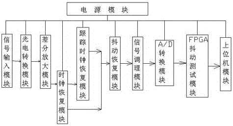
[0052] Such as figure 1 As shown, a device for SDH (Synchronous Digital Hierarchy) clock jitter test described in the present invention includes a power supply module, a signal input module, a photoelectric conversion module, a differential amplifier module, a clock recovery module, a tracking clock recovery module, and a jitter Recovery module, signal conditioning module, A / D conversion module, FPGA jitter test module, PXI bus control module and host computer module;

[0053] The power supply module is used for signal input module, photoelectric conversion module, differential amplification module, clock recovery module, tracking clock recovery module, jitter recovery module, signal conditioning module, A / D conversion module, FPGA jitter test module, PXI bus Power supply for control module and upper computer module;

[0054] The signal input module is used to receive SDH optical signals of different rates to be detected;

[0055] The photoelectric conversion module is used ...


PUM


Abstract

The invention discloses a device and a method for an SDH (Synchronous Digital Hierarchy) clock jitter test. The device comprises a power module, a signal input module, a photovoltaic conversion module, a differential amplification module, a clock recovery module, a tracking clock recovery module, a jitter recovery module, a signal conditioning module, an A / D (Analog / Digital) conversion module, a FPGA (Field Programmable Gate Array) jitter test module, a PXI (PCI extensions for Instrumentation) bus control module and an upper computer module. Firstly, the device adopts the FPGA jitter test module to omit expensive test instruments and save the cost of the SDH clock jitter test. Secondly, the device adopts an integrated clock recovery chip ADN2812, a differential amplifier ADL5566, an interface chip PCI9054 and the like, so that the area and the complexity of a test circuit are reduced, and the use of a PLL (Phase Locked Loop) circuit is reduce. Finally, the device adopts a way that the upper computer module controls and tests the FPGA jitter test module to reduce the use of an analog circuit and cause a SDH clock jitter test result to be more reliable.

Description

technical field [0001] The invention relates to the field of SDH clock jitter, in particular to a device and method for testing SDH clock jitter. Background technique [0002] Jitter test is one of the core contents of digital clock signal integrity test in SDH (Synchronous Digital Hierarchy), and it is one of the most important measurement parameters of SDH signal quality test; in digital synchronous communication network, the jitter of transmission clock affects the system Synchronization, excessive jitter may also directly lead to bit errors, or reduce the signal-to-noise ratio of the signal, so it is very important to test the jitter of the clock of the SDH signal. However, when traditionally measuring the jitter of the SDH clock, it is often necessary Expensive instruments are used to generate data streams with jitter components, which greatly increases the cost of SDH clock jitter measurement; on the other hand, in order to load jitter, many new circuits are added, whi...

Claims


Application Information

Patent Timeline
IPC IPC(8): H04J3/06
Inventor 段美霞白娟陆桂明姚淑霞袁胜韩珂王红梅常呈果江勇
Owner NORTH CHINA UNIV OF WATER RESOURCES & ELECTRIC POWER
Learn More