
Binding post connection structure of grounding leading line

A technology of grounding lead wires and terminals, which is applied in connection, conductive connection, clamping/spring connection, etc. It can solve the problems of difficult connection, inconvenient test work, and inability to disassemble the terminal, so as to eliminate potential safety hazards and facilitate test work. , the effect of fast and convenient connection

Inactive Publication Date: 2015-12-16
CHANGZHOU POWER SUPPLY OF JIANGSU ELECTRIC POWER +3
View PDF4 Cites 0 Cited by
  • Summary
  • Abstract
  • Description
  • Claims
  • Application Information

AI Technical Summary

Problems solved by technology

Although the connection between the terminal and the lead wire is firmly welded, there are some shortcomings. 1. The fastening plate, that is, the terminal is flat, and the terminal is provided with a connection hole connected to the grounding bar of the equipment. The terminal after welding must be It is on the same plane as the grounding bar of external electrical equipment, so the terminal block is directional, which makes it difficult to connect in any direction between the terminal block and the grounding bar of external electrical equipment
2. During the test work, the terminals cannot be disassembled, which brings inconvenience to the test work

Method used


Image

  • Binding post connection structure of grounding leading line
  • Binding post connection structure of grounding leading line
  • Binding post connection structure of grounding leading line

Examples


Embodiment 1

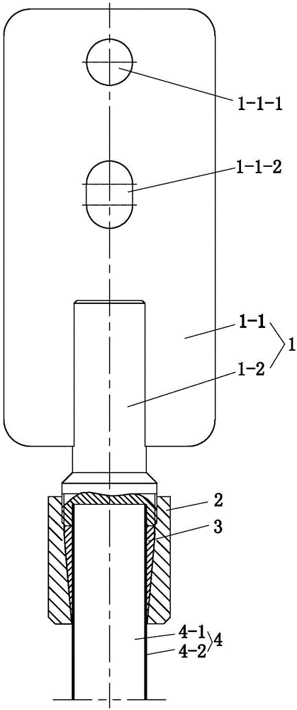
[0016] See Figure 1 to Figure 6 , the present embodiment has lead-in wire 4 and connection terminal 1, lead-in wire 4 is made up of steel mandrel 4-1 and stainless steel sheath 4-2 that tightly wraps its periphery. The terminal 1 is composed of an upper steel rectangular plate 1-1 and a lower steel cylinder 1-2. The steel cylinder 1-2 is stepped, thin at the top and thick at the bottom. A central hole 1-2-1 is provided on the bottom surface of the steel cylinder 1-2. The steel rectangular plate 1-1 of the connecting terminal 1 and the steel The cylinder 1-2 is integral, that is, formed by one-time machining.

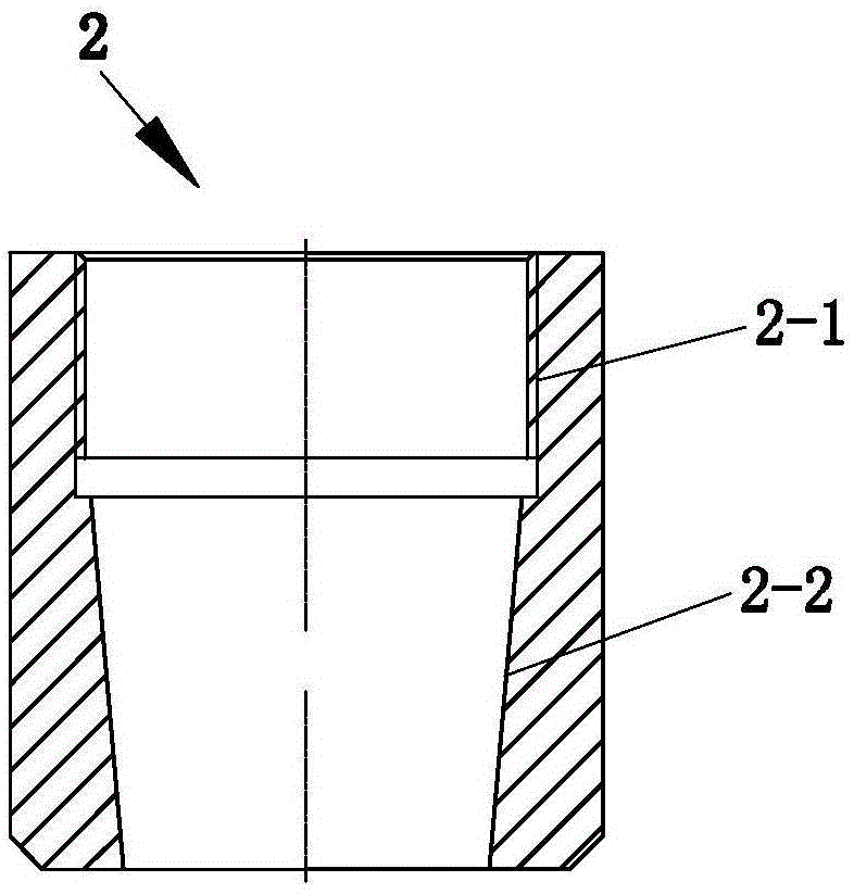
[0017] The terminal 1 is set on the lead wire 4 by using the central hole 1-2-1. The lower part of the steel cylinder 1-2 is provided with an external thread, and the lead wire 4 is covered with a nut 2. The upper part of the inner hole of the nut 2 is 2- 1 is provided with an internal thread, the bottom 2-2 of the inner hole of the nut has a taper, the nut 2 is threa...


PUM


Abstract

Provided is a binding post connection structure of a grounding leading line, including a leading line and a binding post. The binding post is composed of an upper part steel rectangular plate and a lower part steel cylinder. The bottom surface of the steel cylinder is provided with a central hole; the binding post sleeves the leading line through the central hole; the steel cylinder of the binding post is provided with external thread; a nut sleeving the leading line is in threaded connection with the external thread part of the steel cylinder of the binding post; the inner hole lower part of the nut has conicity; a three-jaw grasper is arranged between the nut and the leading line, wherein lower parts of three jaws of the three-jaw grasper have conicity, and the conicity of the three-jaw grasper matches the conicity of the nut. The binding post connection structure can be connected by means of a common tool, thereby reducing requirements for a construction tool; as a result of threaded connection, the binding post connection structure is convenient to assemble and disassemble, and the installation direction of a binding post can be changed randomly, thereby realizing the rapid and convenient installation with an electrical equipment grounding bar in any direction; in addition, the binding post connection structure facilitates test work, and the three-jaw grasper guarantees connection reliability.

Description

[0001] The patent application of the present invention is a divisional application of the invention patent application with the patent application number 201310136006.7, the application date is April 18, 2013, and the title is "connecting terminal connection structure for stainless steel composite ground lead wire". technical field [0002] The invention relates to a connection terminal connection structure of a ground lead wire. Background technique [0003] The stainless steel composite material ground lead wire is generally rod-shaped. At present, the connection between the lead wire terminal and the ground bar of the external electrical equipment is usually arc welding. The utility model patent of China Authorized Notice No. CN202172131U discloses a conductive connecting plate for lead wires. The conductive connecting plate includes a fastening plate and a connecting pipe for leading wires. There is a notch on the upper end surface of the fastening plate, and the leading...

Claims


Application Information

Patent Timeline
Patent Type & Authority Applications(China)
IPC IPC(8): H01R11/11H01R4/50
CPCH01R4/5091H01R11/11
Inventor 吴鸿飞张劲松马振国周明
Owner CHANGZHOU POWER SUPPLY OF JIANGSU ELECTRIC POWER
Learn More