A multi-connector outdoor base station antenna
A base station antenna and multi-connector technology, which is applied in the field of communication, can solve problems such as unsatisfactory, expensive, and height adjustment of the antenna, and achieve good reception and acceptance effects
- Summary
- Abstract
- Description
- Claims
- Application Information
AI Technical Summary
Problems solved by technology
Method used
Image
Examples
Embodiment 1
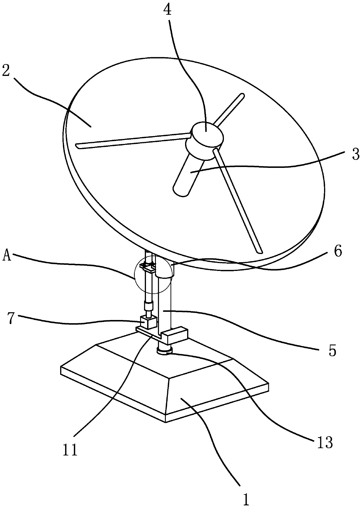
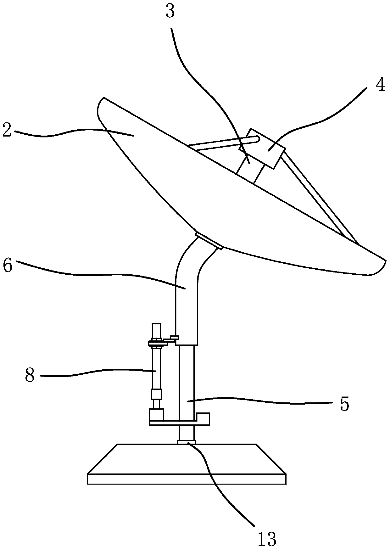
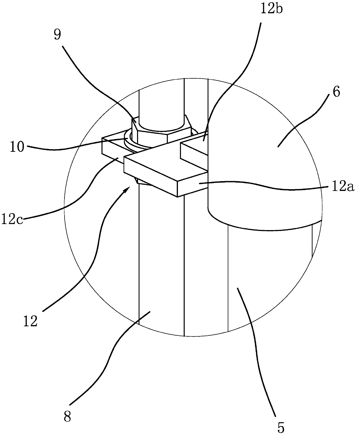
[0024] like figure 1 and figure 2 As shown, a multi-connector outdoor base station antenna includes a base 1 and a transmitting pot 2 arranged on the base 1 . A waveguide 3 is pierced and fixed in the launching pot 2 , a feed source 4 is fixed at the end of the waveguide 3 , and an integrated circuit board is fixed inside the waveguide 3 . Between the base 1 and the firing pot 2, a mounting device capable of mounting the firing pot 2 on the base 1 is provided, wherein the mounting device includes a column 5 vertically arranged on the base 1 and a mounting column 6 arranged on the column 5, One end of the mounting post 6 is fixed on the launching pot 2, and the other end of the mounting post 6 is provided with a mounting hole, and the column 5 is passed through the mounting hole. One end of the mounting column 6 is fixed on the launching pot 2 by bolts and nuts 9, so as to facilitate loading and unloading.
[0025] like image 3 As shown, a lifting and positioning mechanis...
Embodiment 2
[0030]The structure and principle of this embodiment are basically the same as that of Embodiment 1, the difference is that: in Embodiment 1, the lifting and positioning mechanism includes a stepper motor, screw mandrel, nut and bearing 1; and in this Embodiment 2, The lifting and positioning mechanism is a cylinder, and a mounting plate is sleeved and fixed on the column. The cylinder body of the cylinder is fixed on the mounting plate. The piston rod of the cylinder is vertically upward and the end of the piston rod is fixedly connected with the mounting column. The cylinder fixed on the mounting plate can drive the rotating mounting column to move up and down relative to the vertical column through the piston rod, so as to realize the height adjustment of the mounting column. The cylinder body of the cylinder is fixedly connected with the mounting plate through screws, and the piston rod of the cylinder is fixedly connected with the mounting column through screws, bolts and ...
Embodiment 3
[0032] The structure and principle of the present embodiment are basically the same as those of the first embodiment, the difference being: in the first embodiment, the lifting positioning mechanism includes a stepper motor, a screw mandrel, a nut and a bearing; and in the third embodiment, The lifting and positioning mechanism includes a gas spring, and a mounting plate is sleeved and fixed on the column. The lower end of the gas spring is fixed on the mounting plate, and the upper end of the gas spring is vertically upward and fixedly connected with the mounting column through a positioning block. The gas spring fixed on the mounting plate can drive the rotating mounting column to move up and down relative to the column through the piston rod, so as to realize the height adjustment of the mounting column. A threaded hole is provided on the positioning block, and several positioning holes are provided on the mounting column, and positioning bolts are threadedly connected in th...
PUM
 Abstract
Description
Claims
Application Information
 - R&D
- Intellectual Property
- Life Sciences
- Materials
- Tech Scout
- Unparalleled Data Quality
- Higher Quality Content
- 60% Fewer Hallucinations
Browse by: Latest US Patents, China's latest patents, Technical Efficacy Thesaurus, Application Domain, Technology Topic, Popular Technical Reports.
© 2025 PatSnap. All rights reserved.Legal|Privacy policy|Modern Slavery Act Transparency Statement|Sitemap|About US| Contact US: help@patsnap.com


