
Array substrate, touch control display device and driving method thereof

A technology of array substrate and touch driving electrodes, which is applied in static indicators, optics, instruments, etc., can solve the problems of increasing cost and many control signals, and achieves easy design, enhances driving signal strength, and avoids the problem of driving signal attenuation. Effect

Active Publication Date: 2015-12-16
XIAMEN TIANMA MICRO ELECTRONICS +1
View PDF3 Cites 19 Cited by
  • Summary
  • Abstract
  • Description
  • Claims
  • Application Information

AI Technical Summary

Problems solved by technology

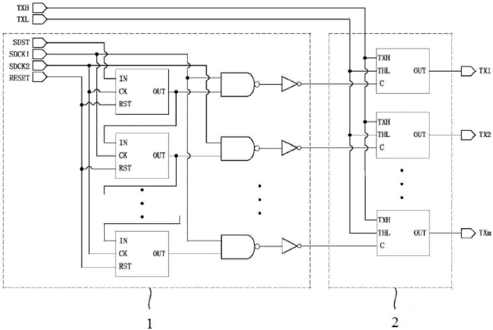
[0004] Additionally, from figure 1 It can also be seen that the signal input terminal (such as figure 1 There are more SDST, SDCK1, SDCK2, RESET, TXH and THL) in it, so that the control signal output by the integrated circuit (IC) that controls it is more, which increases the cost of the IC

Method used


Image

  • Array substrate, touch control display device and driving method thereof
  • Array substrate, touch control display device and driving method thereof
  • Array substrate, touch control display device and driving method thereof

Examples


Embodiment Construction

[0021] Example embodiments will now be described more fully with reference to the accompanying drawings. Example embodiments may, however, be embodied in many forms and should not be construed as limited to the embodiments set forth herein; rather, these embodiments are provided so that this disclosure will be thorough and complete, and will fully convey the concept of example embodiments to those skilled in the art. The same reference numerals denote the same or similar structures in the drawings, and thus their repeated descriptions will be omitted.

[0022] The described features, structures, or characteristics may be combined in any suitable manner in one or more embodiments. In the following description, numerous specific details are provided in order to give a thorough understanding of embodiments of the invention. However, those skilled in the art will appreciate that the technical solutions of the present invention may be practiced without one or more of the specific...


PUM


Abstract

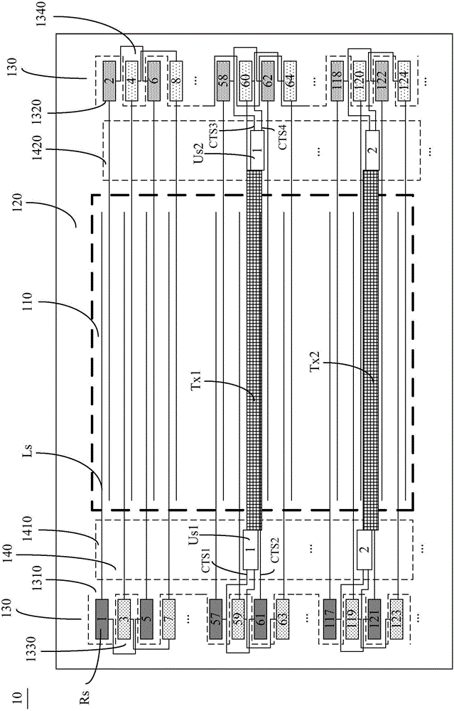
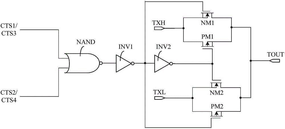
The invention provides an array substrate, a touch control display device and a driving method thereof. The array substrate comprises a grid drive circuit and a touch control drive circuit arranged in a non-display area. The touch control drive circuit comprises multiple stages of touch control selection output units. Each stage of touch control selection output unit comprises two gating signal input ends, and secondary triggering signal output ends of two adjacent shifting registers in the grid drive circuit provide gating signals. The array substrate provides a simplified touch control drive circuit, thereby being easy to realize design of a narrow frame, reducing signal input ends and lowering IC cost. All touch control drive electrodes can be scanned once in each half frame, so that two times of frame frequency of point report rate is realized. The two stage of touch control selection output unit can simultaneously provide touch control signals at two ends of each touch control drive electrode, thereby effectively preventing driving signal attenuation caused by driving signal provision by a single side, and enhancing the intensity of the driving signal.

Description

technical field [0001] The present invention relates to the technical field of touch display, in particular to an array substrate, a touch control device including the array substrate and a driving method thereof. Background technique [0002] In the existing HybridIn-Cell (Hybrid In-Cell, HIC) touch display screen, the touch sensing (RX) electrodes are usually set on the side of the Color Filter (CF) substrate away from the liquid crystal layer, and the TFT array The common (Common) electrodes on the inner side of the substrate are divided into multiple pieces as touch driving (TX) electrodes. In order to prevent the display driver and touch driver from interfering with each other, all TX signals are output at VCOM level during the display time; and during the touch scan period, each level of TX electrodes outputs N pulse signals, and the TX signals One row output, N is determined by the number of gate lines and the number of TX electrodes. [0003] figure 1 It is a sche...

Claims


Application Information

Patent Timeline
Patent Type & Authority Applications(China)
IPC IPC(8): G06F3/041
CPCG09G2300/0408G09G2354/00G06F3/0412G09G3/3677G09G2310/0286G06F3/04166G06F3/0446G02F1/133308G02F1/13338G02F1/133514G02F1/134309G02F1/1368G02F1/136286
Inventor 孙莹许育民
Owner XIAMEN TIANMA MICRO ELECTRONICS
Learn More