
Method and device for controlling electronic equipment

A technology for electronic equipment and control electronics, which is applied in the direction of data processing power supply, etc., can solve the problems of increasing system power consumption and increasing system power consumption, and achieve the effect of reducing system power consumption

Inactive Publication Date: 2015-12-16
LENOVO (BEIJING) CO LTD
View PDF3 Cites 5 Cited by
  • Summary
  • Abstract
  • Description
  • Claims
  • Application Information

AI Technical Summary

Problems solved by technology

When the CPU frequently receives system trigger events, the CPU operating frequency will frequently increase from one operating frequency to the highest operating frequency, which will increase system power consumption accordingly, especially when the CPU operating frequency is frequently increased from the lowest operating frequency to In the case of the highest operating frequency, the power consumption of the system will increase greatly

Method used


Image

  • Method and device for controlling electronic equipment
  • Method and device for controlling electronic equipment
  • Method and device for controlling electronic equipment

Examples


Embodiment Construction

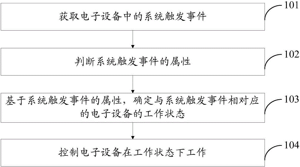
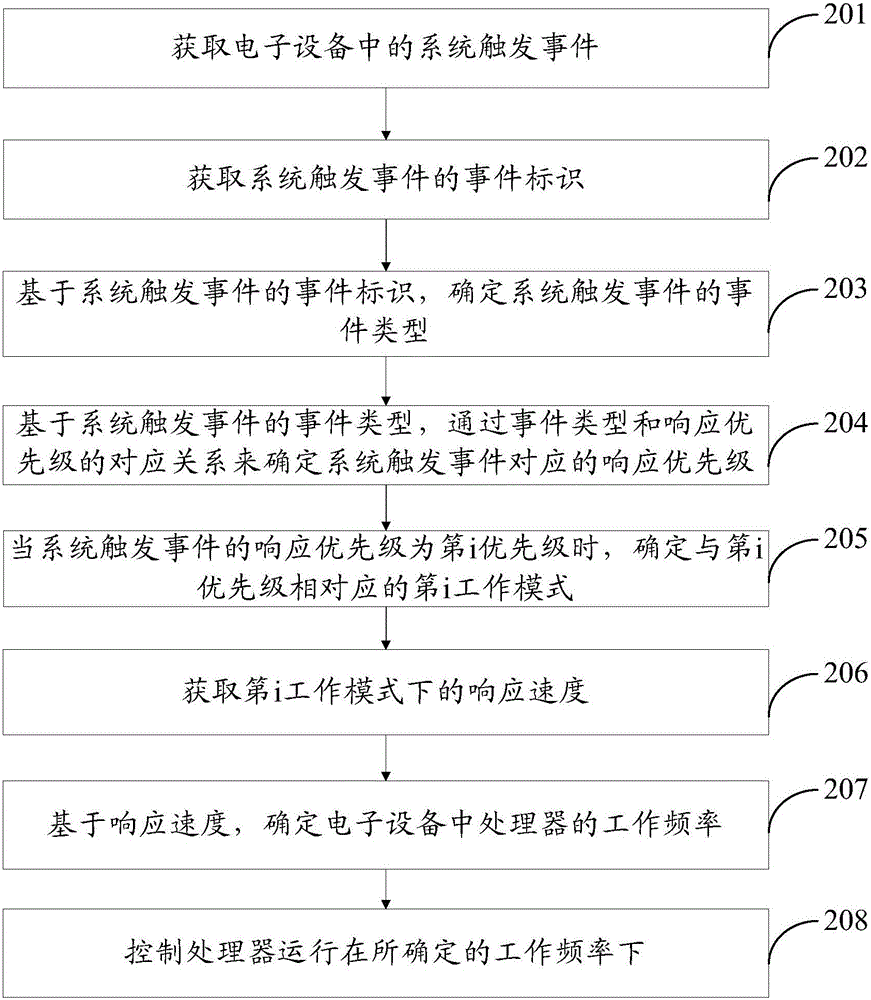
[0045] The core idea of ​​the method and device for controlling electronic equipment provided by the embodiments of the present invention is: based on the attributes of the system trigger event, configure the electronic equipment with a working state that matches the attribute of the system trigger event, and in the matching working state, the electronic device The processor can run at an operating frequency that matches the attributes of the system triggering event, so as to reduce the probability that the operating frequency of the processor is directly increased from the lowest operating frequency to the highest operating frequency, thereby reducing system power consumption. Moreover, the processor of the electronic device can run at a working frequency that matches the attributes of the system trigger event, so the response speed of the electronic device can meet the requirements of the system trigger event, thereby achieving the best performance in terms of system response ...


PUM


Abstract

The invention provides a method and a device for controlling electronic equipment. After a system trigger event in the electronic equipment is acquired, the attribute of the system trigger event can be determined; and a working state corresponding to the system trigger event is determined based on the attribute of the system trigger event, so that the electronic equipment is controlled to work in the working state corresponding to the system trigger event. Namely, after any one system trigger event is acquired, the working state matched with the attribute of the system trigger event is configured for the electronic equipment, a processor of the electronic equipment can run under a working frequency matched with the attribute of the system trigger event in a matched working state, so that the system power consumption is lowered. The processor can run under the working frequency matched with the attribute of the system trigger event, so that the response speed of the electronic equipment can meet the requirement of the system trigger event, and balance between system response speed and system power consumption is realized.

Description

technical field [0001] The present invention relates to the technical field of equipment control, and more specifically, to a method and device for controlling electronic equipment. Background technique [0002] At present, electronic equipment is in consideration of the performance of the operating system, and the control CPU (Central Processing Unit, central processing unit) adopts an (ondemand) frequency modulation system on demand, wherein the frequency modulation system on demand refers to increasing the operating frequency of the CPU after receiving any system trigger event , so that the CPU can respond to system trigger events in a timely manner. [0003] In the prior art, in order to enable the CPU to respond to system triggering events in a timely manner, the operating frequency of the CPU is raised to a certain frequency every time any system triggering event is received. For example, when receiving a system trigger event that a key is pressed, the operating frequ...

Claims


Application Information

Patent Timeline
Patent Type & Authority Applications(China)
IPC IPC(8): G06F1/32
Inventor 刘荫夏陈实
Owner LENOVO (BEIJING) CO LTD
Learn More