
Method for automatic detection of silicon tuner rf FILTER

An automatic detection and tuner technology, applied in the field of RFFILTER detection, can solve problems such as high cost investment and achieve the effect of reducing investment

Active Publication Date: 2018-08-14
SICHUAN CHANGHONG ELECTRIC CO LTD
View PDF6 Cites 0 Cited by
  • Summary
  • Abstract
  • Description
  • Claims
  • Application Information

AI Technical Summary

Problems solved by technology

[0004] The present invention overcomes the deficiencies of the prior art, and provides a method for automatic detection of a silicon tuner RF FILTER, which is used to solve the technical problem of high cost investment in the existing detection methods

Method used


Image

  • Method for automatic detection of silicon tuner rf FILTER

Examples


Embodiment Construction

[0030] The present invention will be further described in detail below in conjunction with examples, but the embodiments of the present invention are not limited thereto.

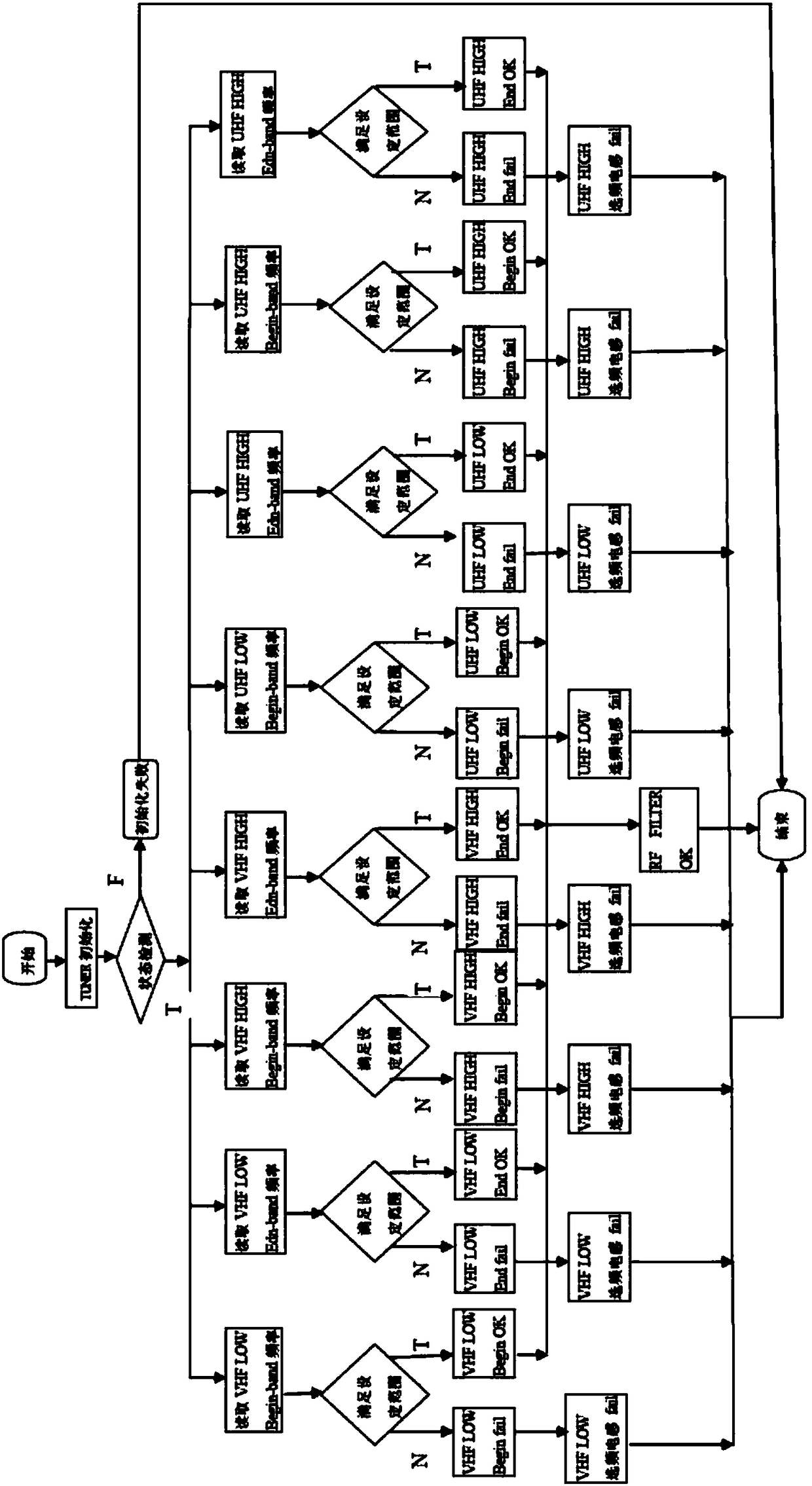
[0031] see figure 1 As shown, a silicon tuner RF FILTER inductance automatic detection method, read the actual RF FILTER frequency selection range in the TUNER chip register by entering the IIC bus, and compare with the internal setting frequency selection range to determine whether the frequency selection range is Meet the design requirements.

[0032] And according to the comparison results between the actual frequency selection range of RF FILTER and the frequency selection range set by the software, it can be judged whether the peripheral frequency selection inductor of the Tuner meets the design requirements.

[0033] Due to differences among manufacturers of tuner solutions, RF FILTER segments are also different. In this embodiment, the tuner RFFILTER frequency selection bandpass filter is divided i...


PUM


Abstract

The invention discloses a silicon tuner RF FILTER automatic detection method. RF FILTER frequency selecting range is read via a control IIC bus and compared with the set selecting frequency deviation range and judgment is performed. The judgment result is fed back via a display interface, and a certain inductor with problems can be determined through the result. Therefore, investment of equipment and human resources in RF FILTER detection can be reduced for television manufacturers so that production cost can be reduced, production efficiency can be enhanced and product quality can be enhanced.

Description

technical field [0001] The invention relates to the technical field of RF FILTER detection, in particular to a method for automatic detection of a silicon tuner RF FILTER. Background technique [0002] RF FILTER is the frequency selection network in the tuner. At present, the LC resonant filter composed of the built-in adjustable capacitor of the tuner chip and the external frequency selection inductor is generally used to realize the frequency selection of each frequency band. In order to ensure the performance of the frequency selection network, the frequency selection filter should be able to ensure that each band can work normally from the corresponding frequency range of the tuner VHF to UHF. However, due to the limitations of the inductor manufacturing process, the inductance generally has deviations, and the consistency is difficult to maintain. At the same time, the parasitic elements (such as SMD series resistors) inevitably brought about by PCB wiring will also aff...

Claims


Application Information

Patent Timeline
Patent Type & Authority Patents(China)
IPC IPC(8): H04N17/00
Inventor 陈元伟史青朱大林王承健
Owner SICHUAN CHANGHONG ELECTRIC CO LTD
Learn More