Rapid inserting connector for oil pipe and mounting and dismounting methods for rapid inserting connector

A plug-in joint and oil pipe technology is applied in the field of automobile fuel supply system, which can solve the problems of high manufacturing cost of quick-plug joint mold, inconvenient installation and disassembly, and cost of easily damaged parts, etc. The effect of preventing leakage

Active Publication Date: 2015-12-16
ANHUI JIANGHUAI AUTOMOBILE GRP CORP LTD
View PDF5 Cites 8 Cited by
  • Summary
  • Abstract
  • Description
  • Claims
  • Application Information

AI Technical Summary

Problems solved by technology

[0004] The purpose of the present invention is to provide an oil pipe quick-plug joint and its installation and disassembly method. By redesigning the overall structure of the quick-insert joint, the complexity of the quick-insert joint can be reduced, thereby solving the problem of high manufacturing cost of the quick-insert joint mold and problems of installation. The problem of inconvenient disassembly and disassembly; at the same time, the strength of the push-in joint can be increased through structural changes, thereby solving the problem that the joint body of the push-in joint is easily damaged and the cost of parts is increased.

Method used


Image

  • Rapid inserting connector for oil pipe and mounting and dismounting methods for rapid inserting connector
  • Rapid inserting connector for oil pipe and mounting and dismounting methods for rapid inserting connector
  • Rapid inserting connector for oil pipe and mounting and dismounting methods for rapid inserting connector

Examples


Embodiment Construction

[0044] Embodiments of the present invention are described in detail below, examples of which are shown in the drawings, wherein the same or similar reference numerals designate the same or similar elements or elements having the same or similar functions throughout. The embodiments described below by referring to the figures are exemplary only for explaining the present invention and should not be construed as limiting the present invention.

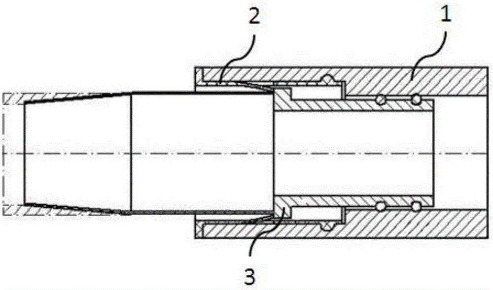
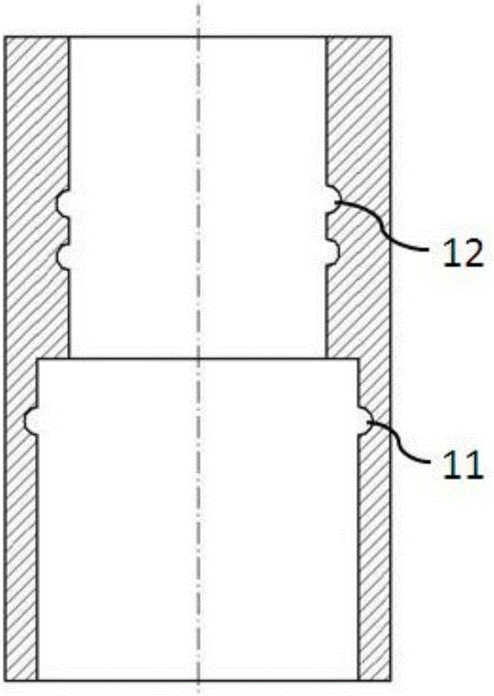
[0045] Such as Figure 2 to Figure 6As shown, a fuel pipe push-in joint of the present invention includes: a first joint body 1, a second joint body 2 and a snap ring 3; the first joint body 1 is a cylindrical structure, and a stepped hole is provided along the axis, The small hole end of the stepped hole is matched with the second joint body 2, and the large hole end of the stepped hole is matched with the snap ring 3; the second joint body 2 is a cylindrical structure, which includes a tubing connecting portion 21, a clamping portion 2...


PUM


Abstract

The invention discloses a rapid inserting connector for an oil pipe. The rapid inserting connector comprises a first connector body, a second connector body and a clamping ring. The first connector body is of a cylindrical structure, and a step hole is formed along the axis of the first connector body, wherein the small-hole end of the step hole is matched with the second connector body, and the large-hole end of the step hole is matched with the clamping ring. The second connector body is of a cylindrical structure and comprises an oil pipe connecting part, a clamping and connecting part and an inserting and connecting part. The clamping ring is of a cylindrical structure and is inserted in the first connector body. The outer wall face of the clamping ring is matched with the inner wall face of the large-hole end of the first connector body, and the inner wall face of the clamping ring is matched with the outer wall face of the second connector body. According to the rapid inserting connector for the oil pipe, the mold manufacturing cost can be effectively reduced by simplifying the structure, and mounting and dismounting convenience is substantially improved. Meanwhile, the strength of the rapid inserting connector can be increased through the change of the structure, the fault rate of the rapid inserting connector for the oil pipe is greatly reduced, the work efficiency of the rapid inserting connector for the oil pipe is improved, and the service life of the rapid inserting connector for the oil pipe is prolonged.

Description

technical field [0001] The invention belongs to the technical field of automobile fuel supply systems, and in particular relates to a fuel pipe quick-plug joint and its installation and disassembly methods. Background technique [0002] The fuel supply system refers to the pipeline used to connect the fuel tank, diesel filter, engine inlet and outlet ports in the diesel engine fuel system. In this system, the fuel pipes connecting various parts must have good sealing, otherwise the engine will not start normally, and even fuel leakage will occur. At present, the fuel supply system of heavy-duty trucks has gradually promoted the use of quick-plug fuel pipes, and the structural complexity, manufacturing cost, and convenience of maintenance of the quick-plug connectors have also attracted much attention. [0003] The existing oil pipe quick-plug structure such as figure 1 As shown, it is mainly composed of a push-in connector 101 and a special interface 102. The push-in conne...

Claims


Application Information

Patent Timeline
IPC IPC(8): F16L37/084
CPCF16L37/084
Inventor 黄海岭尚晓虎廖少龙
Owner ANHUI JIANGHUAI AUTOMOBILE GRP CORP LTD
Why Eureka
Try Eureka