Power-lossing type joint rotation electromagnetic lock device

An electromagnetic lock and joint technology, applied in the direction of brake actuators, etc., can solve the problems of electronic circuit interference, susceptibility to electromagnetic fields, high and low temperature and other environmental factors, and affect the normal operation of equipment, so as to increase safety, lock and The unlocking switching process is smooth and the torque is large

Inactive Publication Date: 2015-12-16
TIANJIN JINHANG INST OF TECH PHYSICS
View PDF6 Cites 7 Cited by
  • Summary
  • Abstract
  • Description
  • Claims
  • Application Information

AI Technical Summary

Problems solved by technology

This type of rotary electromagnetic lock has a simple structure, but it is easily affected by environmental factors such as electromagnetic fields, high and low temperatures, etc.
From the perspective of electromagnetic compatibility, there is an electromagnetic field during the electromagnetic working process of this type, which will interfere with the electronic circuit and affect the normal operation of the equipment, especially for medical electronic equipment and robots with strict electromagnetic compatibility requirements.

Method used


Image

  • Power-lossing type joint rotation electromagnetic lock device
  • Power-lossing type joint rotation electromagnetic lock device

Examples


Embodiment approach

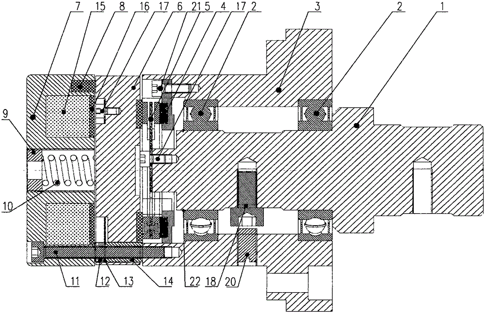
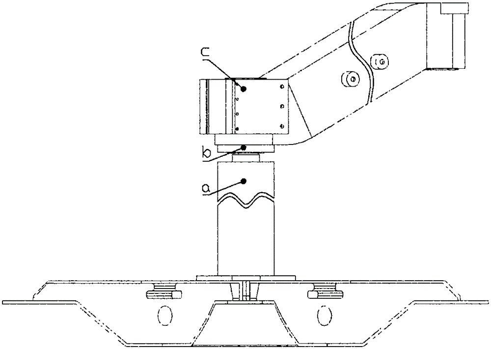
[0017] Such as figure 2 As shown: the electromagnetic lock device b is fixed to the column a through the threaded hole of the main shaft 1, and is fixed to the cantilever c through the five countersunk holes of the bearing seat 3. When the electromagnetic lock device b is not energized, it is in a locked state. The cantilever c has a certain rotational torque relative to the main column a and cannot rotate freely. When the external torque exceeds the design torque of the electromagnetic lock device b, it can rotate with resistance. When the electromagnetic lock device b is connected to 24V AC or DC power through the switch, according to the above working process, the electromagnetic lock device b is in the unlocked state. At this time, the cantilever c has no rotational torque relative to the main column a, and can rotate freely without resistance. In the unlocked state, when the rotation of the cantilever c needs to be limited within a circle, the limit screw 20 can be screw...


PUM


Abstract

The invention discloses a power-lossing type joint rotation electromagnetic lock device which successfully realizes power-off brake of an electromagnetic lock through dual axial and circumferential fixation. The electromagnetic lock is not provided with a permanent magnet structurally; the braking torque can be steplessly adjusted as required; damping is increased during the altering process of the brake and unlocking states, so that vibration and impact of a movable armature are greatly reduced; the torque is not affected by the external environments such as high and low temperature, an electromagnetic field and the like; the working performance indexes (including braking torque, pass power, working stability at high and low temperature, continuous service life and the like) are verified by experiments, reach the advanced level, and have greater market application prospects and advantages.

Description

technical field [0001] The invention belongs to a joint mechanism rotation locking / unlocking device, in particular to a power-off type joint rotation electromagnetic lock device, especially suitable for medical equipment, robots and other rotating joint structures that need to be locked when power is lost, and unlocked when power is turned on without affecting manually adjusted device. Background technique [0002] The joint rotation electromagnetic lock is widely used in medical equipment, robots and other mechanical devices with a rotary joint structure, to realize the rapid locking / unlocking state switching of the rotating mechanism, so as to ensure the flexible movement and precise positioning of each actuator. Especially for medical surgical instruments or devices, most rotary joints require strict position locking when rotating to a certain angle, and mechanical clearance or clearance is not allowed. Most rotary electromagnetic locks in the prior art are based on the ...

Claims


Application Information

Patent Timeline
Patent Type & Authority Applications(China)
IPC IPC(8): F16D65/14
Inventor 孙海刚孟军合李景
Owner TIANJIN JINHANG INST OF TECH PHYSICS
Why Eureka
Try Eureka