
Pump-valve compound control hydraulic system for full-hydraulic straightener

A hydraulic system and composite control technology, which is applied in the direction of fluid pressure actuation system components, mechanical equipment, fluid pressure actuation devices, etc., can solve the problems of low transmission efficiency and low efficiency of the system, achieve fast response speed, low cost, The effect of increasing the degree of automation and control performance

Inactive Publication Date: 2015-12-16
TAIYUAN UNIVERSITY OF SCIENCE AND TECHNOLOGY
View PDF9 Cites 8 Cited by
  • Summary
  • Abstract
  • Description
  • Claims
  • Application Information

AI Technical Summary

Problems solved by technology

The hydraulic system of the traditional full-hydraulic straightening machine adopts the valve control system, which has the advantages of high precision and fast response, but the efficiency is low. The three-phase asynchronous motor is mainly used to drive the quantitative hydraulic pump to output constant pressure and constant flow.
The four pressing oil cylinders belong to high pressure, heavy load, and large flow during the straightening process of the steel plate, and belong to low pressure and small flow in the process of return and standby. The pressure and flow of the system are set according to the maximum power of the hydraulic cylinder, and the controlled object is The load force and speed of the roller box are changing in real time, resulting in a large amount of throttling loss and overflow loss in the system, and the transmission efficiency of the system is low
According to statistics, the energy loss caused by high pressure throttling loss is as high as 36% - 68%.

Method used


Image

  • Pump-valve compound control hydraulic system for full-hydraulic straightener
  • Pump-valve compound control hydraulic system for full-hydraulic straightener
  • Pump-valve compound control hydraulic system for full-hydraulic straightener

Examples


Embodiment Construction

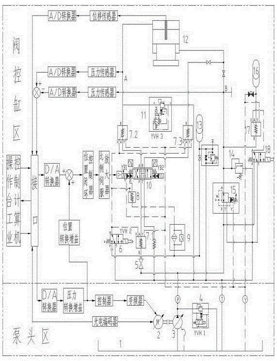
[0029] As shown in Figure (1): the variable frequency motor 2 forms a hydraulic power source through variable frequency speed regulation and the variable hydraulic pump 3. Since the hydraulic pumps all stipulate the minimum speed (n>200r / min), when the flow rate is controlled by this invention, when the flow rate When it is small, it is controlled by changing the displacement of the pump; when the flow rate is greater than the minimum value, it is controlled by changing the speed of the electric frequency motor, and when the pressure is controlled, it is controlled by changing the displacement of the pump. The straightening process is a process of heavy load, large flow, and high response. The dynamic response speed of the variable frequency motor is slow. In order to prevent the flow of the hydraulic pump from instantly failing to meet the response requirements of the system, an accumulator group 13 is connected to the outlet of the hydraulic pump. , as an energy storage eleme...


PUM


Abstract

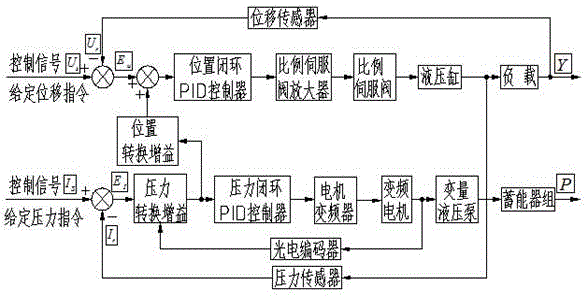
The invention relates to a pump-valve compound control hydraulic system for a full-hydraulic straightener, and belongs to the technical field of electro-hydraulic servo of full-hydraulic straighteners. The pump-valve compound control hydraulic system is characterized in that based on the variable frequency electronic technology, a variable frequency motor and a variable pump are used for replacing a common three-phase asynchronous motor and a constant displacement pump, the novel pump-valve compound control hydraulic system is provided by fusing respective advantages of pump control and valve control and combining energy accumulator units, by means of the variable rotating speed and variable displacement compound control, comprehensive indicators of the hydraulic system are increased greatly, noise reduction, high efficiency and energy conservation of the hydraulic system are achieved to the greatest extent, energy can be saved by 20-60%, and efficiency can be improved by 5-30%; by embedding the pressure conversion gain and position conversion gain, triplex control over the position, the flow and the pressure is achieved, the response speed of the hydraulic servo system is increased, and the intelligence degree of the hydraulic servo system is improved.

Description

technical field [0001] The invention belongs to the technical field of electro-hydraulic servo control of a full-hydraulic straightening machine, and in particular relates to a hydraulic system of a full-hydraulic straightening machine with compound control of pumps and valves. Background technique [0002] The full hydraulic straightening machine is one of the important finishing equipment on the medium and heavy plate production line. It mainly controls the four main pressing hydraulic cylinders through the hydraulic system to adjust the lifting of the upper roll box, and then realizes the size of the roll gap during the straightening process of the plate. online dynamic adjustment. The hydraulic system of the traditional full-hydraulic straightening machine adopts a valve control system, which has the advantages of high precision and fast response, but the efficiency is low. It mainly uses a three-phase asynchronous motor to drive a quantitative hydraulic pump to output c...

Claims


Application Information

Patent Timeline
IPC IPC(8): F15B1/04F15B21/04F15B11/08B21D3/00
CPCY02E60/16Y02P70/10
Inventor 黄庆学和东平韩贺永姚艳萍宋浩韦建春
Owner TAIYUAN UNIVERSITY OF SCIENCE AND TECHNOLOGY
Learn More