Bridge-type concentric measuring, adjusting and sealing examination integrated testing instrument
A testing instrument and sealing technology, applied in the directions of measurement, production of fluids, wellbore/well components, etc., can solve problems such as low efficiency, large workload, and increased operation risks, so as to simplify operation procedures, improve testing efficiency, reduce Downhole operation risk and effect of construction cost
- Summary
- Abstract
- Description
- Claims
- Application Information
AI Technical Summary
Problems solved by technology
Method used
Image
Examples
Embodiment 1
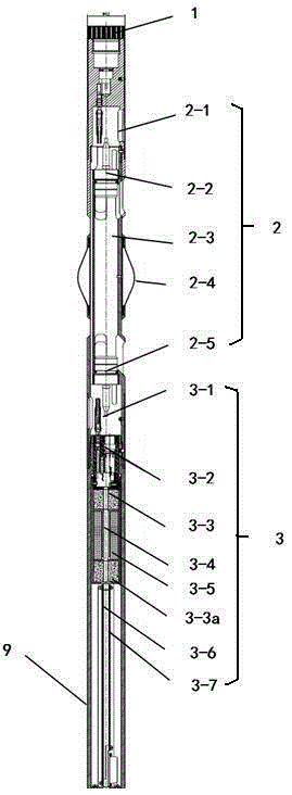
[0023] In order to overcome the problem that in the existing layered water injection process technology, both the seal inspection and the test and adjustment process need to be lowered into the instrument for at least two operations, the workload is relatively large, the efficiency is low, and the operation risk is increased. This embodiment provides a kind of figure 1 and figure 2 The bridge-type concentric test and test seal integrated test instrument shown includes the upper joint 1, the flow measurement mechanism 2, the main control mechanism 3, the power transmission mechanism 4, the tool positioning mechanism 5, the test and test mechanism connected sequentially from top to bottom. Seal switching mechanism 6, seal checking mechanism 7 and flow regulating mechanism 8, an outer cylinder 9 is arranged on the outside of the main body control mechanism 3 and power transmission mechanism 4, the upper end of the outer cylinder 9 is connected with the flow measurement mechanism...
Embodiment 2
[0026] On the basis of Embodiment 1, the flow measurement mechanism 2 includes an information control device 2-1, a flow measurement upper probe 2-2, a flow meter 2-3, and a flow measurement lower probe 2-5 connected sequentially from top to bottom , the lower part of the flowmeter 2-3 is connected to the outer cylinder 9; the power transmission mechanism 4 includes a motor 4-3, a coupling 4-4 and a transmission shaft 4-5 connected sequentially from top to bottom, and the lower part of the transmission shaft 4-5 It is set in the tool positioning mechanism 5; the test and inspection seal switching mechanism 6 includes a lower coupling 6-1 and an upper clutch 6-2, and the lower coupling 6-1 is connected with the lower part of the tool positioning mechanism 5; the sealing inspection mechanism 7 includes a glue Cylinder 7-6, connecting rod 7-7, following rubber cylinder 7-9 and following clutch 7-10, upper clutch 6-2 is connected with connecting rod 7-7, connecting rod 7-7 is con...
Embodiment 3
[0035] On the basis of embodiment 2, the flow measuring mechanism 2 also includes a centralizer 2-4, which is arranged outside the flowmeter 2-3 and connected with the flowmeter 2-3; the flowmeter 2-3 is an ultrasonic flowmeter, and the flow measurement signal is converted in the information control device 2-1 to obtain measurement data.
[0036] The main body control mechanism 3 includes a power supply sealing block 3-1, a temperature and pressure sensor 3-2, a control frame 3-6, and a control acquisition mechanism 3-7, which are sequentially set in the outer cylinder 9 from top to bottom. 3-7 is the single-chip microcomputer control unit, which is used to receive various action commands sent by the ground controller, and transmit them to the actuators of each part to perform various downhole operations; the control frame 3-6 is sequentially arranged with An upper magnetic steel 3-3, a coil shaft 3-5, a lower magnetic steel 3-3a, and a magnetic induction coil 3-4 wound on the...
PUM
 Abstract
Description
Claims
Application Information
 - R&D
- Intellectual Property
- Life Sciences
- Materials
- Tech Scout
- Unparalleled Data Quality
- Higher Quality Content
- 60% Fewer Hallucinations
Browse by: Latest US Patents, China's latest patents, Technical Efficacy Thesaurus, Application Domain, Technology Topic, Popular Technical Reports.
© 2025 PatSnap. All rights reserved.Legal|Privacy policy|Modern Slavery Act Transparency Statement|Sitemap|About US| Contact US: help@patsnap.com


