
Hydraulic lifting machine for lifting steel cylinder

A lift, hydraulic technology, applied in the field of lifting steel cylinders, can solve the problems of increasing labor intensity of workers, increasing production costs, and heavy cylinder weight, and achieves a compact structure that reduces labor intensity of workers, facilitates handling of steel cylinders, and Effect

Inactive Publication Date: 2015-12-16
CHENGDU ZHILIAN ENVIRONMENTAL PROTECTION EQUIP
View PDF9 Cites 2 Cited by
  • Summary
  • Abstract
  • Description
  • Claims
  • Application Information

AI Technical Summary

Problems solved by technology

However, the weight of the steel cylinder is large. When lifting the steel cylinder, the usual operation is that two workers stand on both sides of the steel cylinder, one of the workers hugs the upper end of the steel cylinder, and the other hugs the lower end of the steel cylinder, thereby lifting the steel cylinder Lift vertically, and finally one of the workers passes the ear hole of the steel cylinder through the hook to lift the steel cylinder, which undoubtedly increases the labor intensity of the workers and increases the production cost, and in the lifting process, if the operation is improper, It is easy to cause safety hazards

Method used


Image

  • Hydraulic lifting machine for lifting steel cylinder
  • Hydraulic lifting machine for lifting steel cylinder
  • Hydraulic lifting machine for lifting steel cylinder

Examples


Embodiment Construction

[0013] The present invention will be further described below in conjunction with accompanying drawing, protection scope of the present invention is not limited to the following:

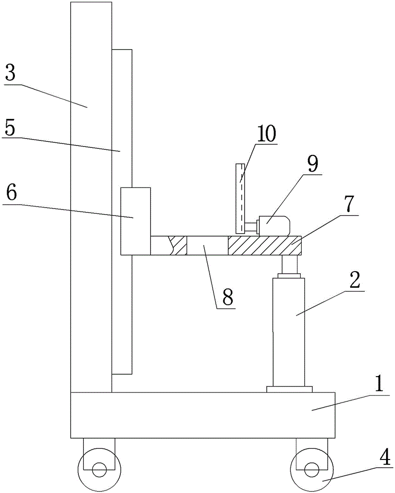
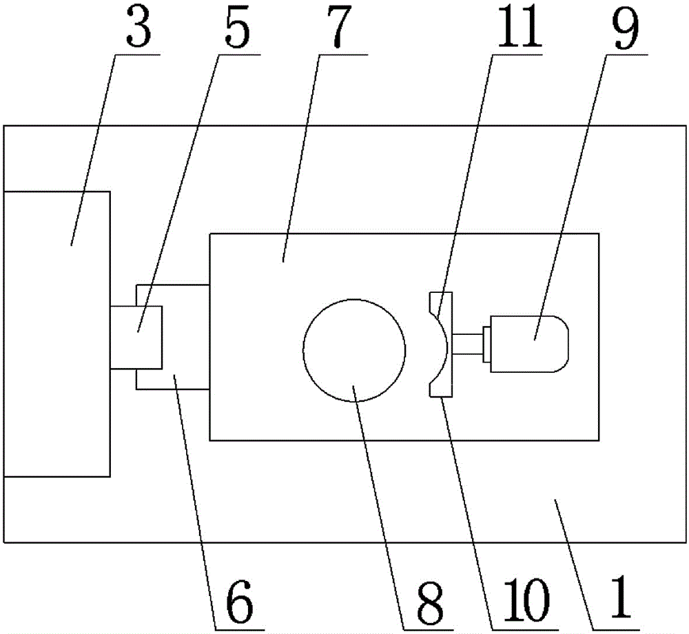
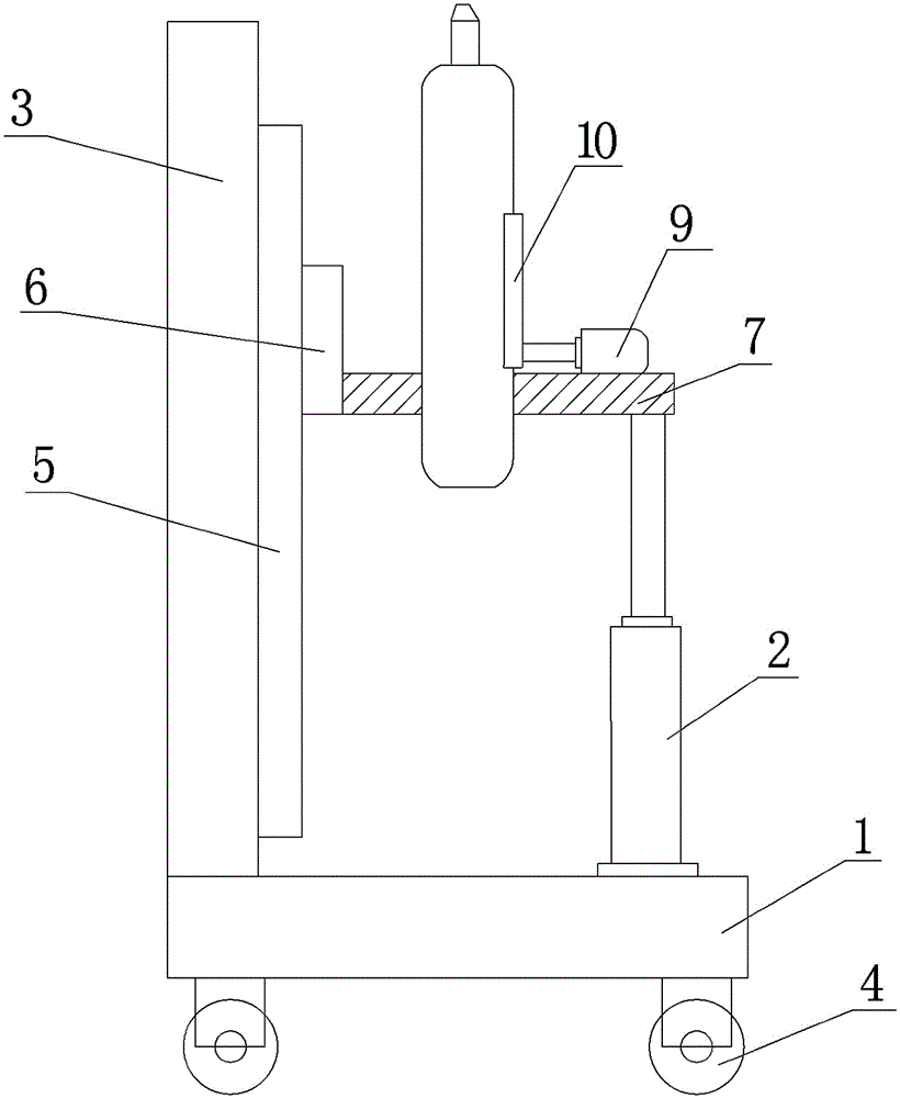
[0014] Such as figure 1 with figure 2 Shown, a kind of lift of hydraulic lifting steel cylinder, it comprises walking trolley 1, vertical oil cylinder 2 and the supporting plate 3 that is arranged on the top of walking trolley 1, and supporting plate 3 is arranged perpendicular to walking trolley, and described support Plate 3 is arranged on the left end of walking trolley 1, and the bottom of walking trolley 1 is fixedly installed with four universal wheels 4, and the right end surface of described support plate 3 is provided with guide rail 5, and guide rail 5 is arranged vertically, and on guide rail 5 Slider 6 is installed.

[0015] Such as figure 1 with figure 2 As shown, the slide block 6 is provided with a steel plate 7, the steel plate 7 is arranged perpendicular to the guide rail 5, th...


PUM


Abstract

The invention discloses a hydraulic lifting machine for lifting a steel cylinder. The hydraulic lifting machine for lifting the steel cylinder comprises a walking trolley (1), a vertical oil cylinder (2) and a support plate (3) arranged on the top of the walking trolley (1), the support plate (3) is arranged at the left end of the walking trolley (1), a guide rail (5) is arranged on the right end face of the support plate (3), a steel plate (7) is arranged on a sliding block (6) and is perpendicular to the guide rail (5), the diameter of a through hole (8) is equal to the external diameter of the steel cylinder, a piston rod of a horizontal oil cylinder (9) is provided with a chuck (10), a semicircular groove is formed in the end face of the chuck (10), a vertical oil cylinder (2) is fixedly installed on the walking trolley (1), the vertical oil cylinder (2) is arranged at the right end of the walking trolley (1), and a piston rod of the vertical oil cylinder (2) is fixed on the steel plate (7). The hydraulic lifting machine for lifting the steel cylinder has the advantages that safety and reliability are achieved, the putaway efficiency of the steel cylinder is improved, the labor intensity of workers is reduced, and the steel cylinder can be carried conveniently.

Description

technical field [0001] The invention relates to the technical field of lifting steel cylinders, in particular to a hydraulic lifting machine for lifting steel cylinders. Background technique [0002] At present, steel cylinders include disposable or refillable mobile pressure containers with different pressures, different volumes, different structural forms and different materials for storing and transporting permanent gases, liquefied gases and dissolved gases. The height of the steel cylinders varies, some steel cylinders are used to hold liquid gases, such as liquid nitrogen, liquid ammonia, liquefied natural gas, liquid oxygen, etc., and some steel cylinders are used to hold industrial gases, such as argon, nitrogen, hydrogen, etc. [0003] In the steel cylinder production plant, the processing technology of the steel cylinder is as follows: firstly cast a steel cylinder with two plates with a cavity, and then weld the two halves. After welding, the outer surface of the ...

Claims


Application Information

Patent Timeline
Patent Type & Authority Applications(China)
IPC IPC(8): B66F7/18B66F7/28
CPCB66F9/06
Inventor 楼晖刘滔曾建清杨国强王睿
Owner CHENGDU ZHILIAN ENVIRONMENTAL PROTECTION EQUIP
Learn More