
Rotary milling device for long-pitch screw machining

A large pitch and screw technology, applied in feeding device, thread cutting device, metal processing, etc., can solve the problems of unstable precision, low efficiency, short service life of machine tools, etc., and achieve the effect of improving efficiency, high efficiency and prolonging service life

Active Publication Date: 2015-12-16
WUHAN NEWWISH TECH
View PDF8 Cites 0 Cited by
  • Summary
  • Abstract
  • Description
  • Claims
  • Application Information

AI Technical Summary

Problems solved by technology

[0005] In the traditional process, there are the following disadvantages: first, the service life of the machine tool is short, usually a new horizontal car can only be used for 3-4 years; High-precision cutters also require high-level operators; the third is low efficiency: taking the main screw processing of a 1000T electric screw press as an example, under normal circumstances, it takes about 100 hours to complete

Method used


Image

  • Rotary milling device for long-pitch screw machining
  • Rotary milling device for long-pitch screw machining
  • Rotary milling device for long-pitch screw machining

Examples


Embodiment Construction

[0030] In order to make the object, technical solution and advantages of the present invention clearer, the present invention will be further described in detail below in conjunction with the accompanying drawings and embodiments. It should be understood that the specific embodiments described here are only used to explain the present invention, not to limit the present invention. In addition, the technical features involved in the various embodiments of the present invention described below can be combined with each other as long as they do not constitute a conflict with each other.

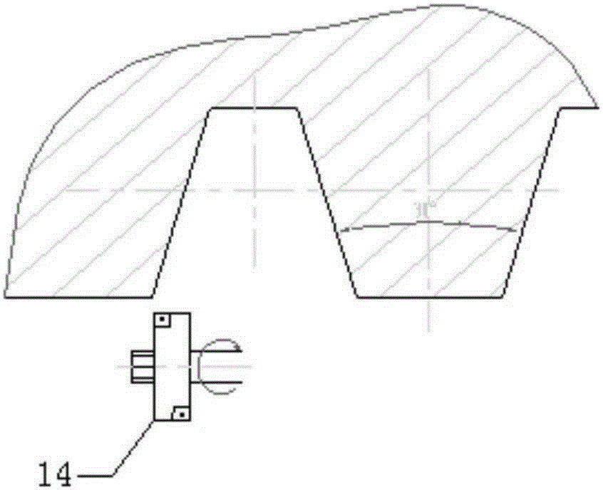
[0031] refer to Figure 3 ~ Figure 6 , a rotary milling device for large-pitch screw processing, including a fixed bracket 1, a moving bracket 2, a main transmission mechanism and a rotation transmission mechanism, wherein,

[0032] The fixed bracket 1 is used to be installed on the carriage of the lathe, so as to move together with the carriage.

[0033] The moving bracket 2 is hinged on the ...


PUM


Abstract

The invention discloses a rotary milling device for long-pitch screw machining. The rotary milling device comprises a fixed support, a movable support, a main transmission mechanism and a rotating transmission mechanism. The movable support is hinged to the fixed support through a hinged shaft. An arc-shaped hole concentric with the hinged shaft is formed in the movable support. The movable support and the fixed support are connected together after a bolt penetrates through the movable support through the arc-shaped hole. The main transmission mechanism comprises a shaft base, a transmission shaft, a milling cutter, a motor and a transmission device. The rotating transmission mechanism comprises a gear rotating shaft, an arc-shaped rack, a gear and a hand wheel assembly. The gear rotating shaft is arranged on the fixed support in a rotatable mode and is parallel to the hinged shaft. The arc-shaped rack is fixedly arranged on the movable support. The gear and the arc-shaped rack are meshed and fixedly arranged at one end of the gear rotating shaft. The hand wheel assembly is arranged at the other end of the gear rotating shaft. The rotary milling device is high in machining efficiency and accuracy, and can greatly save materials.

Description

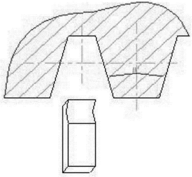
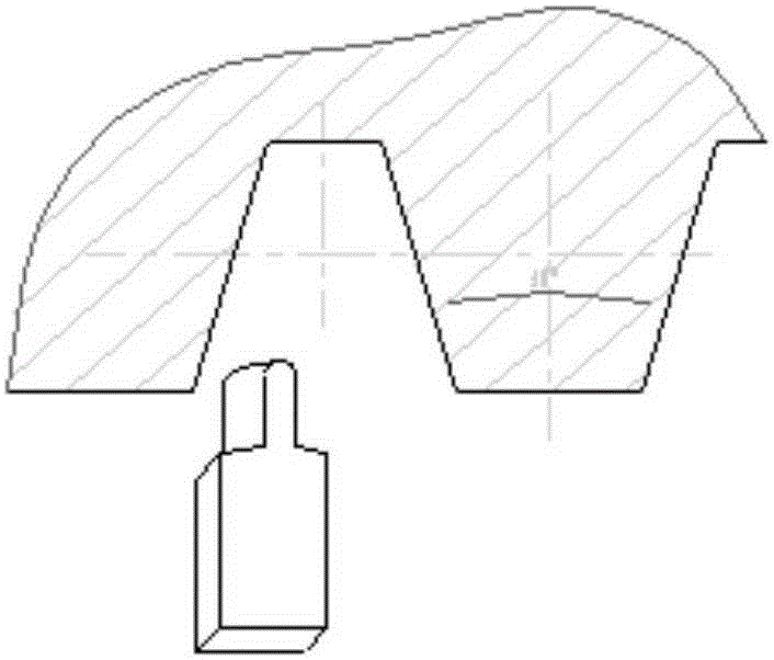
technical field [0001] The invention belongs to the field of electric screw presses, and more specifically relates to a rotary milling device for processing large-pitch screw rods. Background technique [0002] In the prior art, the processing of the main screw of the electric screw press is generally carried out by modifying the ordinary horizontal car, which can reach the slow motion state (0.4-0.8r / min), and realize the slow cutting through the hanger wheel and the slow motor. [0003] The main screw of the electric screw press is a trapezoidal thread with multiple heads and large pitch. In the traditional process, when cutting at a slow speed, first use a specially ground white steel knife to open the groove, the amount of cutting each time is 0.40mm, the speed is 6r / min, and the rough turning is carried out. The cutting method is as follows: figure 1 .Then use a special grinding tool for 15° cutting, the cutting method is as follows figure 2 , the workpiece is turned...

Claims


Application Information

Patent Timeline
Patent Type & Authority Applications(China)
IPC IPC(8): B23G1/32B23G1/44B23Q15/22
Inventor 王习斌陈平朱明丽郭亚兰刘丽娟
Owner WUHAN NEWWISH TECH
Learn More