
Acidic waste gas treatment device

A technology for acid waste gas and treatment device, which is applied in the separation of dispersed particles, chemical instruments and methods, separation methods, etc., can solve the problems of large size of waste gas treatment device, high investment and operating costs, and reduce equipment investment and use and maintenance costs. , Small footprint and the effect of reducing the frequency of replacement

Inactive Publication Date: 2015-12-16
SICHUAN UNIV
View PDF4 Cites 2 Cited by
  • Summary
  • Abstract
  • Description
  • Claims
  • Application Information

AI Technical Summary

Problems solved by technology

Existing acid waste gas treatment devices have problems such as large volume of waste gas treatment devices, high initial investment and high operating costs

Method used


Image

  • Acidic waste gas treatment device
  • Acidic waste gas treatment device

Examples


Embodiment 1

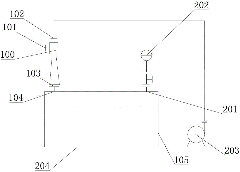
[0032] see figure 1, this embodiment provides an acid waste gas treatment device, including: a liquid storage tank 204 for storing lye, a first gas-liquid mixer for mixing acid waste gas and lye, and a delivery pump for transporting lye 203. Wherein, the first gas-liquid mixer is provided with a first mixing chamber 100, a first liquid inlet 102, a first liquid outlet 103, and a first air inlet 101 for inputting acid waste gas. The first air inlet 101, the first Both the liquid inlet 102 and the first liquid outlet 103 communicate with the first mixing chamber 100 .

[0033] The liquid storage tank 204 is provided with the first output hole 105 and the first input hole 104, the input end of the delivery pump 203 is connected with the first output hole 105, the output end of the delivery pump 203 is connected with the first liquid inlet 102, and the first liquid discharge The port 103 is connected with a first input hole 104 .

[0034] The mixing chamber of the first gas-liq...

Embodiment 2

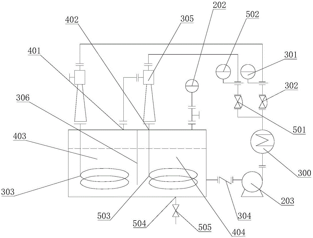
[0039] refer to figure 2 , this embodiment provides an acid waste gas treatment device, including: a liquid storage tank 204 for storing lye, a first gas-liquid mixer for mixing acid waste gas and lye, and a delivery pump for transporting lye 203. Wherein, the first gas-liquid mixer is provided with a first mixing chamber 100, a first liquid inlet 102, a first liquid outlet 103, and a first air inlet 101 for inputting acid waste gas. The first air inlet 101, the first Both the liquid inlet 102 and the first liquid outlet 103 communicate with the first mixing chamber 100 . The liquid storage tank 204 is provided with the first output hole 105 and the first input hole 104, the input end of the delivery pump 203 is connected with the first output hole 105, the output end of the delivery pump 203 is connected with the first liquid inlet 102, and the first liquid discharge The port 103 is connected with a first input hole 104 .

[0040] Because acid-base neutralization will pro...


PUM


Abstract

The invention provides an acidic waste gas treatment device and belongs to the technical field of gas treatment equipment. The acidic waste gas treatment device comprises a liquid storage tank, a first gas-liquid mixer and a conveying pump, wherein the first gas-liquid mixer is provided with a first mixing chamber, a first liquid inlet, a first liquid outlet and a first gas inlet for inputting the acidic waste gas; the first gas inlet, the first liquid inlet and the first liquid outlet are all communicated with the first mixing chamber; a first input hole and a first output hole are formed on the liquid storage tank; an input end of the conveying pump is connected with the first output hole; an output end of the conveying pump is connected with the first liquid inlet; the first liquid outlet is connected with the first input hole. The acidic waste gas treatment device is simple in structure, small in volume, low in use cost and capable of reducing the discharge index and processing cost of the acidic waste gas.

Description

technical field [0001] The invention relates to the technical field of gas treatment equipment, in particular to an acid waste gas treatment device. Background technique [0002] In chemical reaction experiments, various gases are usually produced, such as chlorine, nitrogen oxides, sulfur dioxide, hydrogen sulfide and other acidic waste gases. How to deal with these waste gases, especially acidic waste gases, has become a difficult problem in laboratory waste gas treatment. At present, the treatment methods of acid waste gas mainly include: 1) Dissolution method: pass the waste gas into a solvent, and use the solvent to completely or mostly dissolve the waste gas. 2) Combustion method: Some harmful combustible gases are ignited and burned in the discharge hole to eliminate pollution. For example, carbon monoxide, etc. 3) Neutralization method: For gas with strong acidity or alkalinity, use appropriate alkali or acid to absorb. 4) Adsorption method: select an appropriate ...

Claims


Application Information

Patent Timeline
Patent Type & Authority Applications(China)
IPC IPC(8): B01D53/78B01D53/40
Inventor 郭勇
Owner SICHUAN UNIV
Learn More