
Manufacturing method of antenna and antenna structure

A manufacturing method and technology of antenna structure, which are applied in the direction of radiating element structure, antenna support/installation device, etc., can solve the problems of wasting mobile phone space, labor cost and high material cost, achieve small use space, reduce artificial assembly errors, guarantee Effects of Stability and Reliability

Active Publication Date: 2015-12-09
SHENZHEN SUNWAY COMM
View PDF3 Cites 5 Cited by
  • Summary
  • Abstract
  • Description
  • Claims
  • Application Information

AI Technical Summary

Problems solved by technology

[0006] The technical problem to be solved by the present invention is to overcome the existing problems of high labor cost and material cost and waste of mobile phone space, and provide a manufacturing method and antenna structure of the antenna

Method used


Image

  • Manufacturing method of antenna and antenna structure
  • Manufacturing method of antenna and antenna structure
  • Manufacturing method of antenna and antenna structure

Examples


Embodiment 1

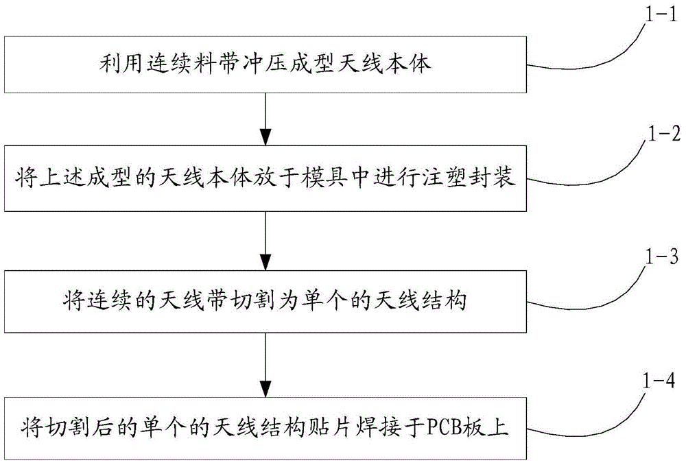
[0040] Please refer to figure 1 , Embodiment 1 of the present invention is:

[0041] The invention discloses a method for manufacturing an antenna, and the antenna can be used in various electronic devices such as mobile phones and palmtop computers. include:

[0042] 1-1: The antenna body is stamped and formed with a continuous strip;

[0043] The strip is nickel-nickel metal strip, which has good weldability and is not easy to be corroded.

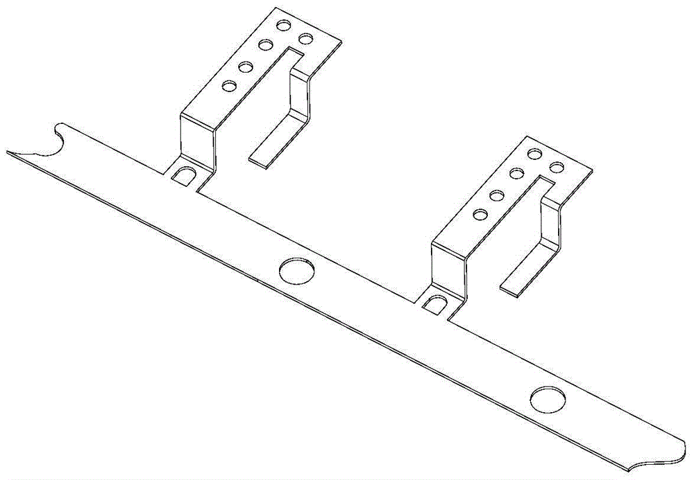
[0044] Refer to attached figure 2 shown, with figure 2 It shows a schematic diagram of the structure of the antenna body formed by stamping the continuous strip; in this step, preferably, the antenna body includes a main body, a first end provided with a welding point for welding with the PCB board, the main body Connected to the first end, preferably, the first end is L-shaped, and the main body includes a second end with a plurality of openings and a third end with a gradient shape.

[0045] 1-2: Put the antenna body formed in ...

Embodiment 2

[0052] An antenna structure can be obtained through the manufacturing method of Embodiment 1, and is suitable for various electronic devices such as mobile phones and palmtop computers. It includes an antenna body and an injection molding part. The antenna body includes a main body covered by the injection molding part, and a first end suspended outside the injection molding part. Preferably, the first end is L-shaped. The bottom surface of the first end is provided with welding points. The first end can be welded to the PCB through the welding point. The main body part includes a second end with a plurality of openings and a third end with a gradient shape; the openings are exposed from the injection molding part and can be used for circuit connection. A groove can be provided on the bottom surface of the injection molding part, and the material of the injection molding part can withstand high temperature above 240°C.

[0053]To sum up, in the present invention, the require...


PUM


Abstract

The present invention discloses a manufacturing method of an antenna. The manufacturing method of the antenna comprises the steps of 1-1: utilizing a continuous material strap to punch and mold an antenna body; 1-2: putting the molded antenna body in the step 1-1 in a die for injection molding and packaging; 1-3: cutting a continuous antenna band into a single antenna structure; 1-4: welding the cut single antenna structure paster on a PCB. According to the present invention, the stable antenna contact can be guaranteed, the assembly efficiency is improved, and the usage space of the antenna in a complete machine is smallest.

Description

technical field [0001] The present invention relates to the technical field of antennas, in particular to an antenna manufacturing method and an antenna structure. Background technique [0002] With the advent of the era of ultra-thin mobile phones, the structural space and manufacturing cost of mobile phone antennas are becoming more and more tight. The previous antenna structure methods can no longer meet the needs of the modern market. The existing antenna fixing method is firstly to dig out a part of the space on the casing to make an antenna bracket, secondly to make antenna lines on the antenna bracket, and then assemble the antenna to the casing and fix it by heat melting or screwing. The O-shaped shrapnel on the PCB version realizes the contact between the PCB version and the antenna. The existing antenna fixing method needs to add hot-melt posts or screws to fix it on the B shell, and needs to add O-shaped shrapnel to achieve contact with the PCB board, which waste...

Claims


Application Information

Patent Timeline
Patent Type & Authority Applications(China)
IPC IPC(8): H01Q1/22H01Q1/36
Inventor 马明灵
Owner SHENZHEN SUNWAY COMM
Learn More