Pulse optimization method and pulse generation circuit for improving cable fault location accuracy

A technology for pulse generating circuit and cable faults, applied in the fault location and other directions, can solve the problems of measurement blind area, easy misjudgment, transmission pulse oscillation, etc., to achieve the effect of easy analysis, high reliability, and suppression of interference

Active Publication Date: 2018-02-06
STATE GRID CORP OF CHINA +2
View PDF9 Cites 0 Cited by
  • Summary
  • Abstract
  • Description
  • Claims
  • Application Information

AI Technical Summary

Problems solved by technology

[0005] At present, the cable fault distance meter designed based on the pulse time domain reflection method has the main shortcomings in waveform acquisition, display and analysis: the pulse voltage wave emitted by the detection instrument has a certain width, due to the output impedance of the instrument and the waveform of the cable If the impedance does not match, there will be a "smearing effect" of the transmitted pulse at the cable measurement end. When the fault point is very close to the measurement end, the reflected pulse at the fault point will overlap with the transmitted pulse, and the starting position of the reflected pulse cannot be found on the waveform. cause significant measurement blind spots, such as figure 2 In addition, the instrument collects and displays the transmitted pulse and the reflected pulse at the same time. When the fault point is far away from the measuring end, due to the attenuation effect of the cable, the amplitude of the reflected pulse at the fault point will be much smaller than the transmitted pulse. In order to improve the reflection of the fault point The pulse amplitude often needs to increase the gain of the instrument amplifier. Doing so often causes the instrument pulse signal acquisition and amplification circuit to saturate, and the so-called "blocking" phenomenon occurs, resulting in signal acquisition distortion, which is not conducive to waveform analysis.
[0006] In order to eliminate the impact of the transmitted pulse on the measurement results and eliminate the "smearing effect", there is also a patented technology that mentions an impedance balance network, such as image 3 As shown, the resistance, capacitance, inductance, pulse transformer and other components are used inside the instrument to simulate the characteristics of the cable impedance network, to achieve the matching between the internal impedance of the instrument and the cable impedance, and to achieve the purpose of eliminating the influence of the transmitted pulse. However, this method cannot solve the above preconditions The signal "blocking" problem of the amplifying circuit; at the same time, because the simulated impedance cannot completely match the real impedance of the cable, and a large number of transformer components are used, when the cable is long, the inductance and capacitance of the cable and the transformer T2 will make the emission pulse formation more serious Oscillation, resulting in messy waveform, unable to distinguish
[0007] In actual measurement, the above shortcomings will make waveform analysis difficult, difficult to determine the start time of the reflected pulse, easy to misjudgment, resulting in unnecessary economic losses

Method used


Image

  • Pulse optimization method and pulse generation circuit for improving cable fault location accuracy
  • Pulse optimization method and pulse generation circuit for improving cable fault location accuracy
  • Pulse optimization method and pulse generation circuit for improving cable fault location accuracy

Examples


Embodiment Construction

[0021] The present invention will be further described below in conjunction with drawings and embodiments.

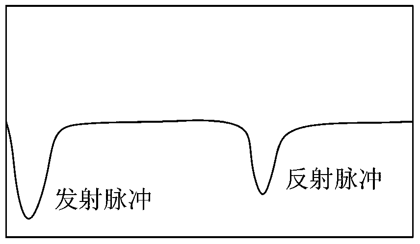
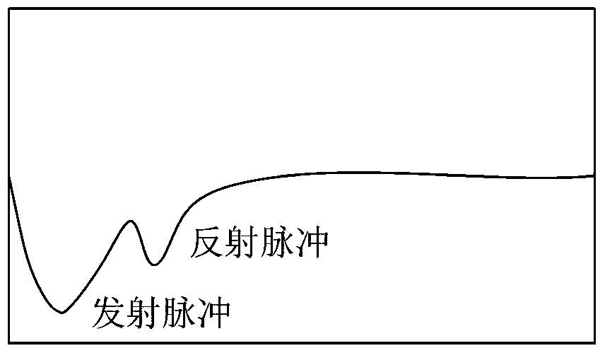
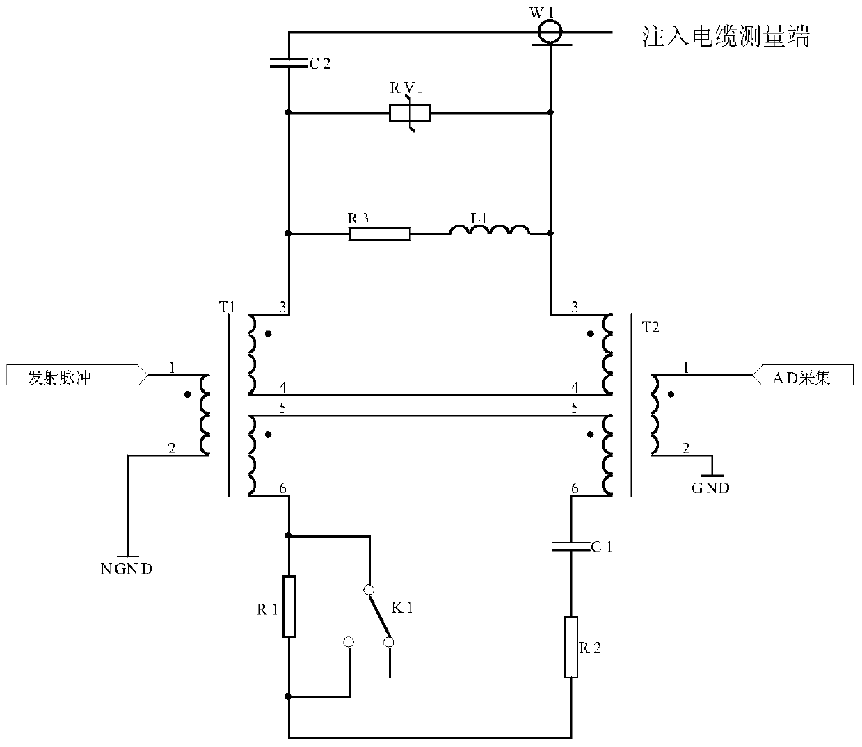
[0022] When the pulse time domain reflection method is used for cable fault location measurement, since the pulse used for analysis is actually only the reflected pulse of the fault point and has nothing to do with the transmitted pulse, a circuit can be designed to generate a transmitted pulse voltage wave, which is divided into two circuits Connected to both ends of the primary side of the pulse transformer, one of the transmission pulses is normally injected into the cable, and the other one cancels the transmission pulse injected into the cable before the AD acquisition of the secondary side of the pulse transformer, so that only the reflected pulse of the fault point is included in the AD acquisition signal, and the No pulses are fired anymore.

[0023] The pulse generation circuit of the present invention comprises a transmission pulse generation circuit 1, a firs...


PUM


Abstract

The invention discloses a pulse optimization method and circuit for improving the accuracy of cable fault distance measurement. When the pulse time domain reflection method is used for cable fault distance measurement, the pulse used for analysis is actually only the reflected pulse of the fault point. It doesn’t matter to transmit pulse, so a circuit can be designed to generate a transmit pulse voltage wave, which is connected to both ends of the primary side of the pulse transformer respectively, one of which transmits the pulse normally into the cable, and the other counteracts the injection before AD acquisition on the secondary side of the pulse transformer The transmission pulse of the cable, in this way, only the reflected pulse of the fault point in the signal collected by AD, without the transmission pulse, the waveform is simple, clear, and easy to analyze; at the same time, it does not affect the normal injection of the transmission pulse signal into the fault cable. The signal input acquisition uses an isolation pulse transformer, which can not only collect the pulse reflection signal on the cable, but also suppress interference, and has high reliability.

Description

technical field [0001] The invention relates to a pulse optimization method and a circuit for improving the accuracy of cable fault distance measurement when the pulse time domain reflection method is used for distance measurement of cable faults, and belongs to the technical field of power electronics. Background technique [0002] Cable power supply has been widely used because of its safety, reliability, and advantages of beautifying cities and industrial and mining layouts. However, with the increasing use of cables, the number of cable faults is also increasing. How to quickly and accurately detect the distance and location of the fault point and find the location of the fault point requires the inspectors to first choose a detection instrument with excellent performance and be able to correctly identify waveform. [0003] Pulse time domain reflectometry is an important method for cable fault location, which is suitable for cable fault location with low resistance and ...

Claims


Application Information

Patent Timeline
Patent Type & Authority Patents(China)
IPC IPC(8): G01R31/08
Inventor 浦仕亮刘伟强何光华徐凯孙柯孔德武杨东兴吴寅雄
Owner STATE GRID CORP OF CHINA
Why Eureka
Try Eureka