Real-time quantification phase retrieval apparatus
A phase recovery and real-time quantitative technology, applied in the field of optical measurement, can solve the problems of reduced practicability and effectiveness, low accuracy of phase reconstruction, sacrifice of camera resolution, etc., to achieve good stability, high resolution and wide application range Effect
- Summary
- Abstract
- Description
- Claims
- Application Information
AI Technical Summary
Problems solved by technology
Method used
Image

Examples
Embodiment 1
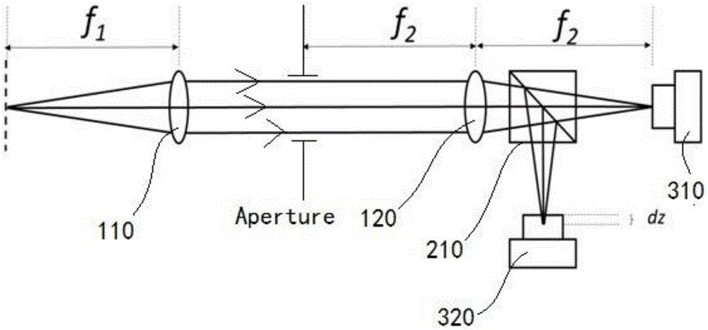
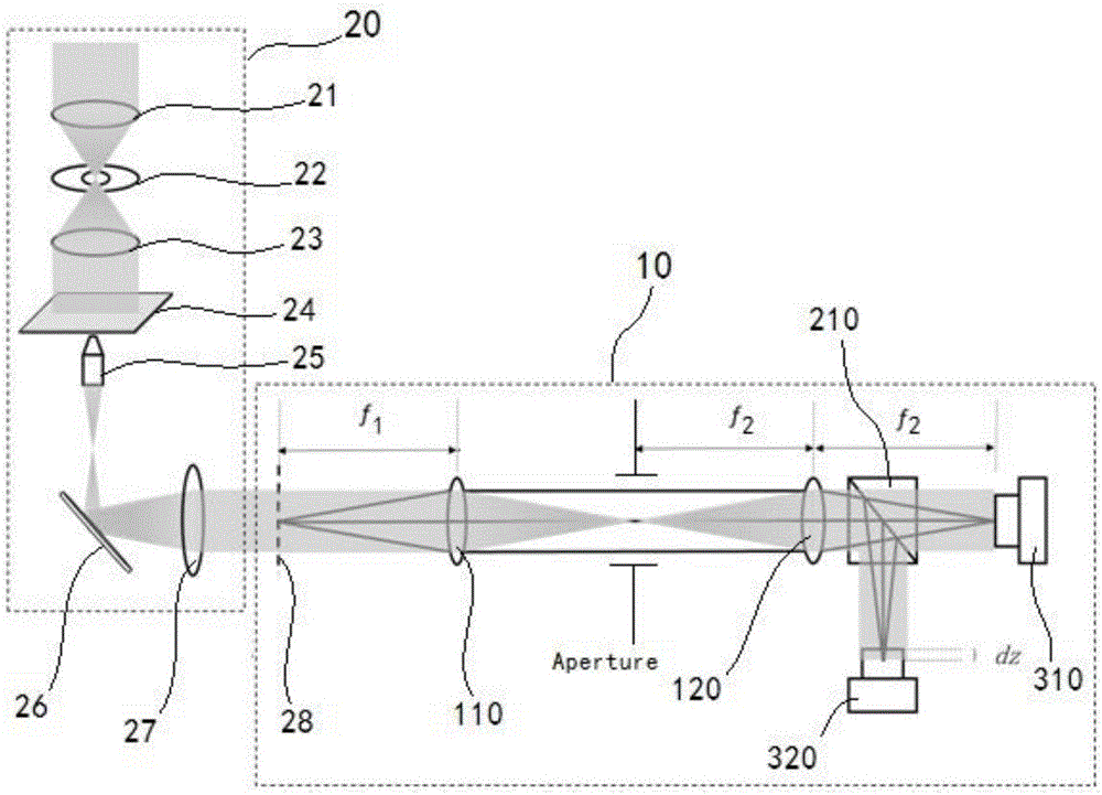
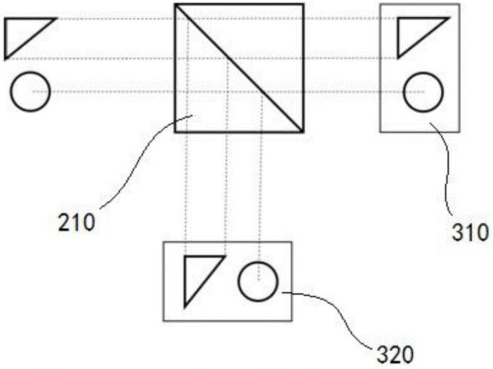
[0044] This embodiment discloses a real-time quantitative phase recovery device, its structural diagram is as follows figure 1 As shown, including the first lens 110 and the second lens 120 whose optical centers are on the same straight line, the first lens 110 and the second lens 120 are arranged in front and back, and the distance between the first lens 110 and the second lens 120 is greater than that of the second lens The focal length of 120, and ensure that the diaphragm of the system is at the front focal plane of the second lens 120. A first beam splitter 210 is disposed behind the second lens 120 , and the first beam splitter 210 is used to split the light emitted from the second lens 120 . At the rear focal point of the second lens 120, a first CCD image sensor 310 is arranged to capture the light passing through the first beam splitter 210; at the lower end of the first beam splitter 210, a second CCD image sensor 320 is arranged to use to capture the light reflecte...
Embodiment 2
[0058] In order to reduce the volume of the device, this embodiment improves on the basis of Embodiment 1, and proposes the following Figure 4 scheme shown. Specifically, the first speed divider 210 is moved between the first lens 110 and the second lens 120 , and the first mirror 410 and the third lens 130 that cooperate with the second CCD image sensor 320 are added. The first speed divider 210 splits the light passing through the first lens 110 (transmitted light and reflected light), and after the transmitted light enters the second lens 120, it enters the first CCD image sensor 310; the reflected light passes through the first mirror 410 and the third lens 130 then enter the second CCD image sensor 320 . In this arrangement, the optical path is changed by the reflector, which makes the whole device more compact and reduces the volume of the whole device.
[0059] In practical applications, in order to ensure that the images captured by the first CCD image sensor 310 an...
Embodiment 3
[0062] In order to improve the precision and accuracy of the phase recovery results, this embodiment improves Embodiment 2, see Figure 5 , the device adds an optical path and a CCD image sensor, and the device captures three images, and calculates through the three images, which greatly improves the accuracy and accuracy of the calculation results.
[0063] Specifically, the second beam splitter 220 is set between the first beam splitter 210 and the first lens 110, and the second reflector 420 and the fourth lens 140 are set to cooperate with the second beam splitter 220 at the same time. Behind the lens 140 is arranged a third CCD image sensor 330 for capturing over-focus images.
[0064] The device of this embodiment captures three images, which are respectively the in-focus image captured by the first CCD image sensor 310, the under-focus image captured by the second CCD image sensor 320, and the captured image obtained by the third CCD image sensor 330. In order to match...
PUM
 Abstract
Description
Claims
Application Information
 - Generate Ideas
- Intellectual Property
- Life Sciences
- Materials
- Tech Scout
- Unparalleled Data Quality
- Higher Quality Content
- 60% Fewer Hallucinations
Browse by: Latest US Patents, China's latest patents, Technical Efficacy Thesaurus, Application Domain, Technology Topic, Popular Technical Reports.
© 2025 PatSnap. All rights reserved.Legal|Privacy policy|Modern Slavery Act Transparency Statement|Sitemap|About US| Contact US: help@patsnap.com