
Coaxial electrolyte flushing method and device for array group electrode micro-hole electromachining

A group electrode and electrical machining technology, which is applied to the field of coaxial flushing of micro-holes of array group electrodes, can solve the problems of different flow rates and poor consistency of group hole sizes, and achieves the effects of improving stability, convenient operation, and simple and compact structure.

Active Publication Date: 2015-12-09
ZHEJIANG UNIV OF TECH
View PDF6 Cites 5 Cited by
  • Summary
  • Abstract
  • Description
  • Claims
  • Application Information

AI Technical Summary

Problems solved by technology

[0006] The purpose of the present invention is to solve the problems of different gap electrolyte flow rates existing in the electromachining of array group holes, resulting in material removal speed in different regions, poor consistency of group hole sizes after processing, etc., and to provide a method that can improve the stability of electromachining, A coaxial liquid flushing method and device for micro-hole electromachining of array group electrodes that are consistent in processing, easy to operate, and easy to implement. This method can ensure that the electrolyte flows into the processing area along the cathode side wall of the tool, and is closed by controlling the electrolyte. The cavity pressure is kept consistent, which can achieve the purpose of consistent electrolyte flow rate at different positions

Method used


Image

  • Coaxial electrolyte flushing method and device for array group electrode micro-hole electromachining
  • Coaxial electrolyte flushing method and device for array group electrode micro-hole electromachining

Examples


Embodiment Construction

[0020] The present invention will be further described below in conjunction with accompanying drawing:

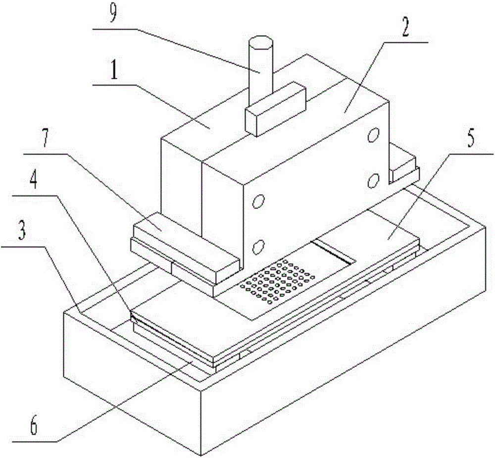
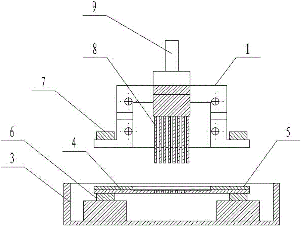
[0021] Such as Figure 1~2 As shown, a coaxial liquid flushing device for electromachining tiny holes of an array group electrode includes an array group electrode 8, an electrolyte sealing cavity, an electrolyte tank 3, an insulating gasket 5, an upper electromagnetic chuck 7 and a lower electromagnetic chuck 6, and the array The cathode end of the group electrode 8 is provided with a plurality of single cathodes distributed in an array, the array group electrode 8 is clamped through the electrolyte sealed cavity, the cathode end of the array group electrode 8 is vertically downward, and the array group electrode 8 is set directly below The workpiece 4 to be processed is fixed with a lower electromagnetic chuck 6 on both sides of the bottom of the workpiece 4 to be processed, an insulating gasket 5 is arranged on the upper end of the workpiece 4 to be processed, and the lo...


PUM


Abstract

The invention discloses a coaxial electrolyte flushing device and method for array group electrode micro-hole electromachining. The coaxial electrolyte flushing device comprises a sealing cavity, array group electrodes, an electrolyte sealing cavity, an electrolyte groove, an insulating gasket and electromagnetic chucks. When the electrolyte sealing cavity is driven by a machine tool main shaft to move to be attached to the insulating gasket, an insulating cavity composed of the electrolyte sealing cavity, the insulating gasket and a workpiece to be machined is formed through the attraction function of the electromagnetic chucks; and the diameter of a single cathode of the array group electrodes is smaller than the diameter of a single hole in the workpiece to be machined, and an electrolyte sealing flow diversion cavity is formed through the cathodes and the corresponding holes. The coaxial electrolyte flushing method is simple and compact in structure, coaxial machining is conducted on micro holes through the array group electrodes, it is guaranteed electrolytes flow into the machining region along the side walls of the cathodes of the array group electrodes, the flowing speed of the electrolytes at different positions is consistent by keeping the pressure of the electrolyte sealing cavity consistent, machining stability and group control machining consistency can be improved, operation is convenient, and implementation is easy.

Description

technical field [0001] The invention relates to the technical field of electrical machining, and belongs to special machining, in particular to a coaxial liquid flushing method and device for micro-hole electrical machining of array group electrodes. Background technique [0002] With the development of science and technology, and the demand for product precision and miniaturization in the industrial field, the miniaturization of mechanical parts has become a research hotspot in the current manufacturing field, and has broad application prospects and prospects in the fields of biomedicine, precision instruments and sensor manufacturing. important research significance. The processing and manufacturing of micro-pore structures with diameters smaller than 1mm is one of the key technologies to achieve these goals. [0003] The methods for realizing micro-hole processing include mechanical processing methods, special processing methods and composite processing methods, and ea...

Claims


Application Information

Patent Timeline
Patent Type & Authority Applications(China)
IPC IPC(8): B23H9/16B23H11/00
Inventor 王明环许雪峰姚春燕彭伟
Owner ZHEJIANG UNIV OF TECH
Learn More