
Brake controller

一种制动控制器、制动力的技术,应用在制动器、制动控制系统、制动组件等方向,能够解决摩擦制动力差等问题

Inactive Publication Date: 2015-12-02
ADVICS CO LTD +1
View PDF10 Cites 3 Cited by
  • Summary
  • Abstract
  • Description
  • Claims
  • Application Information

AI Technical Summary

Problems solved by technology

In such a case, it will be difficult to effectively generate a frictional braking force difference between the steered wheels if a large regenerative braking force is maintained at the steered wheels

Method used


Image

  • Brake controller
  • Brake controller
  • Brake controller

Examples


no. 2 approach

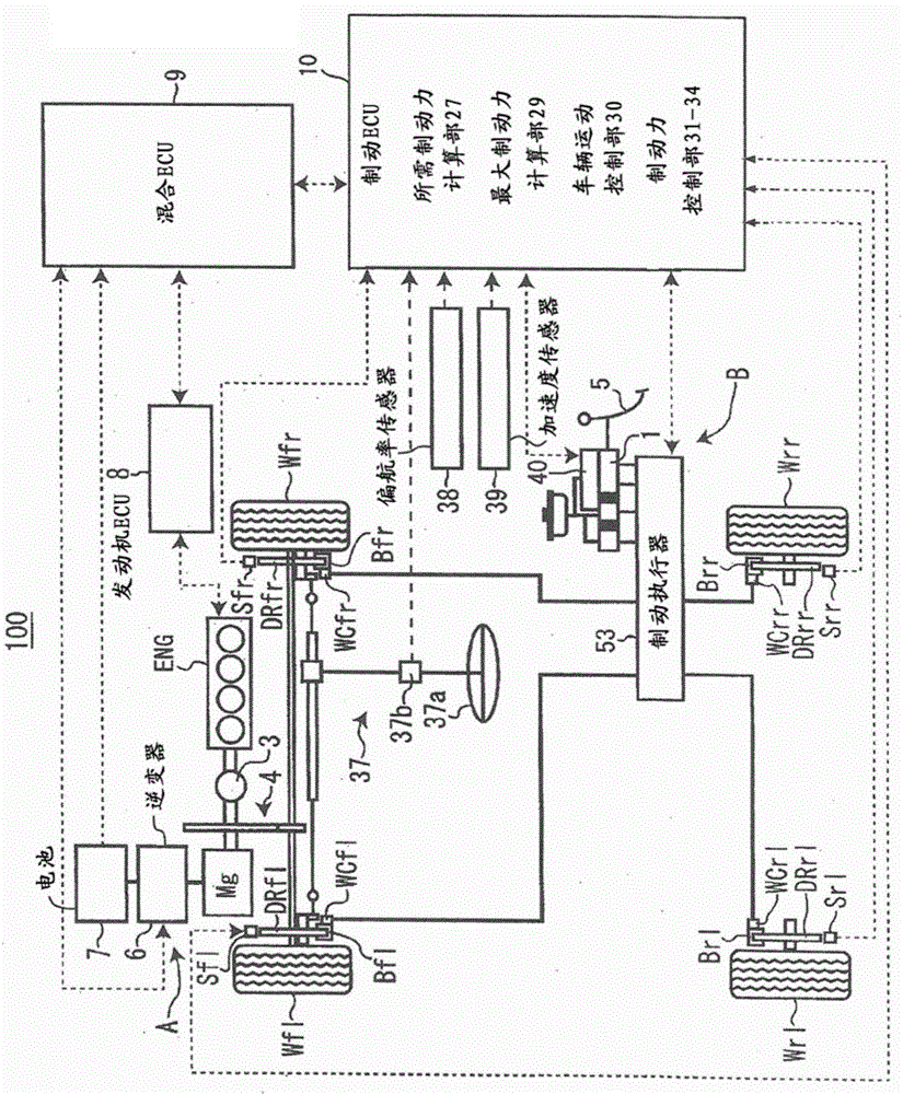
[0159] Next, a second embodiment will be described. According to the second embodiment, there is provided the same braking force control section 31 as the first embodiment (refer to figure 1 ) compared with the partially different braking force control unit 32. In addition to the control performed by the braking force control section 31, the braking force control section 32 sets the regenerative braking force Fcf to be generated at the left and right front wheels Wfl and Wfr to be equal to or smaller than The value obtained from the minimum frictional braking force generated at Wrl (hereinafter referred to as "rear wheel minimum braking force Frmin"). The rear wheel minimum braking force Frmin is set by the vehicle motion control section 30 so that the posture of the vehicle 100 is stabilized during the braking operation. The rear wheel minimum braking force Frmin is set based on the required braking force Fd, steering angle, vehicle speed V, forward / rearward acceleration, l...

no. 3 approach

[0167] Next, a third embodiment will be described. According to the third embodiment, there is provided the same braking force control section 31 of the first embodiment and the braking force control section 32 of the second embodiment (see figure 1 ) compared with the braking force control unit 33 which is partially different. The braking force control section 33 sets the left-right distribution ratio of the braking force Fr to the right rear wheel Wrr / left rear wheel Wrl so that the vehicle attitude is in a steady state. When the braking force control section 33 sets the left-right distribution ratio of the braking force, the friction brake device B is operated based on the left-right distribution ratio to generate the friction braking forces Fmrr and Fmrl.

[0168]At this time, as will be described in detail later, when the frictional braking force Fmrr to be generated at one of the right rear wheel Wrr / left rear wheel Wrl (for example, at the right rear wheel Wrr) exceeds...

no. 4 approach

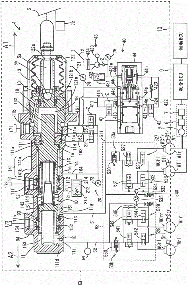
[0181] Next, a fourth embodiment will be described. According to the fourth embodiment, the operation of the friction brake device B is different from that of the corresponding friction brake devices B of the first to third embodiments. Specifically, in the friction brake device B, when the brake actuator 53 is not operated and the brake pedal 5 is depressed, the respective wheel cylinders WCfl, WCfr, WCrl and WCrl of the corresponding wheels Wfl, Wfr, Wrl and Wrr are WCrr provides uniform hydraulic pressure. Friction braking forces Fmfl, Fmfr, Fmrl, and Fmrr corresponding to the uniform hydraulic pressure are generated at the respective wheels Wfl, Wfr, Wrl, and Wrr. This uniform hydraulic pressure is a hydraulic pressure corresponding to the depression of the brake pedal 5 by the operator of the vehicle, and is to be supplied from the master cylinder 1 to each of the wheel cylinders WCfl, WCfr, WCrl, and WCrr. In this fourth embodiment, such a case is assumed.

[0182] Fu...


PUM


Abstract

In order to provide a brake controller that can generate as much regenerative braking force as possible in a vehicle and effectively improve fuel consumption even during times of reduced tire grip force such as when the vehicle is turning, a brake controller is provided with a friction brake device (B), a regenerative brake device (A), a requested braking force calculation unit (27), a vehicle motion control unit (30) for distributing requested braking force (Fd) to the other non-regenerative braking-side left or right wheel of either left and right front wheels (Wfl, Wfr) or left and right rear wheels (Wrl, Wrr), a maximum braking force calculation unit (29) for calculating the maximum braking force (Fmax) of the vehicle wheels (Wfl, Wfr, Wrl, Wrr), and a braking force control unit (31) for calculating regenerative braking force (Fc) generated in the regenerative braking-side left and right wheels within a range that does not exceed the lesser value of the maximum braking force (Fmax) between the regenerative braking-side left and right wheels, on the basis of the requested braking force (Fd) and the distribution of braking force to the non-regenerative braking-side left or right wheel.

Description

technical field [0001] The present invention relates to a brake controller that controls the braking operation of a vehicle by applying both a regenerative braking force and a frictional braking force. Background technique [0002] Conventionally, in EV (Electric Vehicle) and HEV (Hybrid Electric Vehicle), both regenerative braking force and frictional braking force are used as the braking force of the vehicle. In such a vehicle, especially when a braking operation is performed during straight running of the vehicle, the regenerative braking force is used as much as possible by converting the kinetic energy of the vehicle into electric energy, thereby recovering energy efficiently, so that it is possible to improve Vehicle fuel efficiency. However, when the vehicle turns, the grip of the wheels, including the steering wheels of the vehicle, decreases. Therefore, if the amount of regenerative braking force generated at the time of the steering operation of the vehicle is th...

Claims


Application Information

Patent Timeline
Patent Type & Authority Applications(China)
IPC IPC(8): B60T8/17B60L7/24B60T8/1755B60L50/16
CPCB60T1/10B60L3/102B60L3/106B60L7/22B60L11/14B60L15/2009B60L15/2045B60L2240/423B60L2240/463B60L2240/465B60T8/17B60T8/1755B60T2270/604B60W10/00Y02T10/642Y02T10/70Y02T10/7077Y02T10/7283Y02T10/72B60T8/4077B60L50/16B60K6/48B60K2006/4825Y02T10/62Y02T10/64Y02T10/7072B60T8/17551B60T8/17552B60T2270/603
Inventor 冈野隆宏西尾彰高神谷雄介驹沢雅明
Owner ADVICS CO LTD
Learn More