
System for dynamically detecting state of railway retarder based on FPGA

A dynamic detection and deceleration technology, applied in general control systems, control/regulation systems, and program control in sequence/logic controllers, etc., can solve problems such as misjudgment of deceleration quality and lack of deceleration data analysis, etc. To achieve the effect of improving detection efficiency

Inactive Publication Date: 2015-12-02
SHANGHAI UNIV
View PDF10 Cites 2 Cited by
  • Summary
  • Abstract
  • Description
  • Claims
  • Application Information

AI Technical Summary

Problems solved by technology

[0004] The purpose of the present invention is to overcome that most of the state detection of the deceleration jack is manually judged by the way the railway workers step on it with their feet, which not only lacks effective data analysis under the current working state of the deceleration jack, but also affects the quality of the deceleration jack. misjudged the defect

Method used


Image

  • System for dynamically detecting state of railway retarder based on FPGA
  • System for dynamically detecting state of railway retarder based on FPGA
  • System for dynamically detecting state of railway retarder based on FPGA

Examples


Embodiment Construction

[0019] Below in conjunction with accompanying drawing, preferred implementation of the present invention is described in further detail:

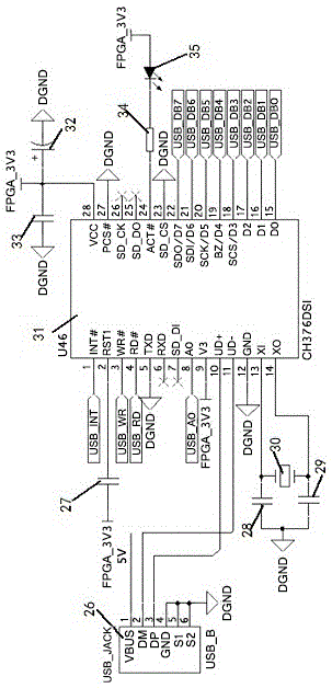
[0020] see figure 1 , the FPGA-based railway deceleration top state dynamic detection system of the present invention includes a central processing unit module 1, an AD acquisition module 2, a USB storage module 3, a PWM differential output module 4, a photoelectric encoding pulse counting module 5, and an RS232 Serial port output display module 6 and a power supply module 7, AD acquisition module 2, USB storage module 3, PWM differential output module 4, photoelectric code pulse counting module 5, RS232 serial port output display module 6, and power supply module 7 are all connected with the central processing unit module 1 connection.

[0021]The CPU module is composed of FPGA control chip, clock circuit, reset circuit, SDRAM memory chip, EPCS memory chip, AS interface circuit and JTAG interface circuit. The control driver drives the se...


PUM


Abstract

The invention provides a system for dynamically detecting the state of a railway retarder based on an FPGA, and the system comprises a CPU module, an AD collection module, a USB storage module, a PWM differential output module, a photoelectric coding pulse counting module, an RS232 serial port output display module, and a power module. The AD collection module, the USB storage module, the PWM differential output module, the photoelectric coding pulse counting module, the RS232 serial port output display module and the power module are respectively connected with the CPU module. The system overturns a conventional mode that a railway retarder is stamped by a foot of a railway worker for experience-based judgment of the quality of the retarder, achieves the full-automatic detection of the railway retarder, fills a gap in the field of automatic detection of the retarder, and greatly improves the detection efficiency of the retarder. The system firstly achieves the data collection of the working state of the retarder, and can be used by the related professionals for effective data analysis.

Description

technical field [0001] The patent of the present invention relates to a dynamic detection system for the state of a railway deceleration jack, especially a dynamic detection system for the state of a railway deceleration top based on FPGA, which belongs to the technical field of automatic detection of railway track systems. Background technique [0002] The retarder is an essential hydraulic device for controlling the speed of the vehicle in the hump speed regulating system of the railway marshalling station. In order to ensure that the retarder can work normally, it is necessary to carry out quality inspection on the retarder installed on the railway to ensure that it is in normal working condition. However, nowadays, the research on the automatic detection system of the retarder is still very scarce. Most of the state detection of the retarder is judged by the manual experience of the railway workers with their feet. It will cause misjudgment of the quality of the retarde...

Claims


Application Information

Patent Timeline
Patent Type & Authority Applications(China)
IPC IPC(8): G05B19/04
CPCG05B19/0423
Inventor 苗中华皱兆光陆鸣超沈一筹魏成雷
Owner SHANGHAI UNIV
Learn More