Liquid crystal photo-alignment control method

A control method and liquid crystal alignment layer technology, applied in optics, nonlinear optics, instruments, etc., can solve the problems of obvious chromatic aberration operation and complexity in the left and right parts of the panel

Active Publication Date: 2015-12-02
BOE TECH GRP CO LTD +1
View PDF6 Cites 2 Cited by
  • Summary
  • Abstract
  • Description
  • Claims
  • Application Information

AI Technical Summary

Problems solved by technology

[0006] The technical problem to be solved by the present invention is to provide a method for controlling the optical orientation of liquid crystals, so as to overcome the defect

Method used


Image

  • Liquid crystal photo-alignment control method
  • Liquid crystal photo-alignment control method
  • Liquid crystal photo-alignment control method

Examples


Embodiment Construction

[0035] The present invention will be described in detail below in conjunction with the accompanying drawings and embodiments.

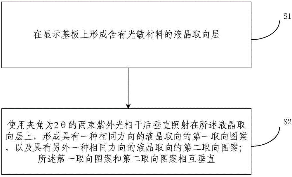
[0036] Such as figure 1 As shown, the embodiment of the present invention provides a method for controlling the optical alignment of liquid crystals, including:

[0037] Step S1, forming a liquid crystal alignment layer containing a photosensitive material on the display substrate;

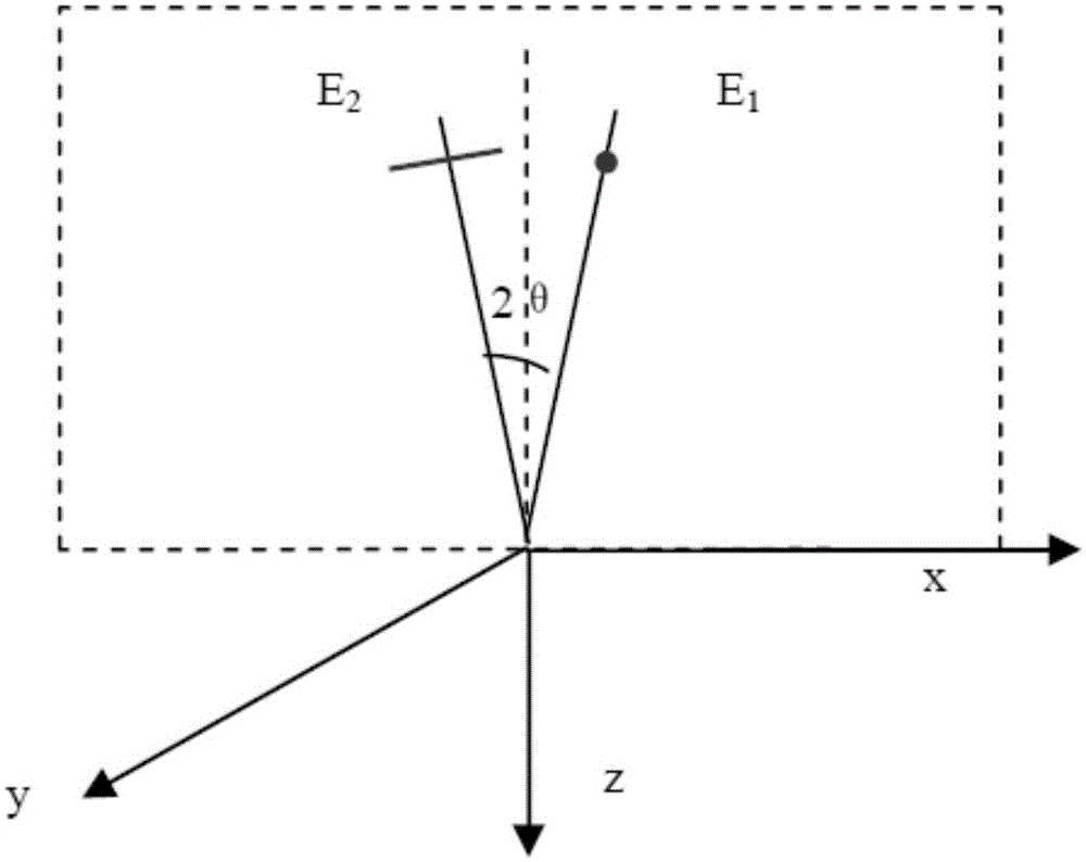
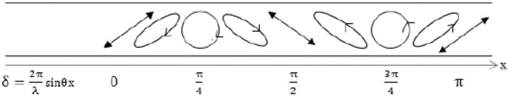
[0038] Step S2, using two beams of ultraviolet light with an included angle of 2θ to coherently irradiate the liquid crystal alignment layer vertically to form a first alignment pattern with one liquid crystal alignment in the same direction, and another liquid crystal alignment with the same direction The second alignment pattern; the first alignment pattern and the second alignment pattern are perpendicular to each other;

[0039] Wherein, the plane where the two beams of ultraviolet light are located is perpendicular to the plane where the liquid crystal alignment la...


PUM


Abstract

The invention relates to the technical field of display, in particular to a liquid crystal photo-alignment control method. The method specifically includes the steps that a liquid crystal alignment layer containing a photosensitive material is formed on a display substrate; after coherence of two ultraviolet light beams with the included angle being 2theta, the ultraviolet light beams vertically irradiate on the liquid crystal alignment layer, first alignment patterns and second alignment patterns are formed, the first alignment patterns have liquid crystal alignment in the same direction, the second alignment patterns have another liquid crystal alignment in the same direction, and the first alignment patterns and the second alignment patterns are perpendicular to each other. According to the liquid crystal molecule photo-alignment control method, liquid crystal molecules are aligned through the double-alignment pattern vertical structures close to 45 degrees, vertical dual-domain liquid crystal alignment is formed through one-time interference exposure by means of a two-beam interference method (without mask), product quality is improved to the largest extent, and the processing period is shortened.

Description

technical field [0001] The invention relates to the field of display technology, in particular to a method for controlling optical alignment of liquid crystals. Background technique [0002] Liquid crystal photo-alignment technology uses polarized ultraviolet light (wavelength 250nm ~ 350nm or so) to irradiate the liquid crystal alignment layer containing photosensitive materials, and the anisotropic energy of polarized ultraviolet light makes the photosensitive material synthesize or degrade along the direction of polarized light energy, forming a liquid crystal alignment layer. Anisotropic side chains can achieve the purpose of photo-orientation. [0003] Photo-orientation is a non-contact alignment method. Compared with the traditional rubbing process, it does not damage the substrate and avoids the dust generated during the rubbing process or the static electricity that can damage the TFT. In addition, the uniformity of the photo-orientation is also better than that of t...

Claims


Application Information

Patent Timeline
IPC IPC(8): G02F1/1337
CPCG02F1/133788G02F1/133746
Inventor 张洪术
Owner BOE TECH GRP CO LTD
Why Eureka
Try Eureka