
Downhole power cable insulation monitoring device

A cable insulation and monitoring device technology, applied in directions such as fault locations, can solve problems such as difficult implementation, low sensitivity, and low sensitivity, and achieve the effects of avoiding economic losses, ensuring operational safety, and improving continuity

Inactive Publication Date: 2015-12-02
苏州市新瑞奇节电科技有限公司
View PDF6 Cites 14 Cited by
  • Summary
  • Abstract
  • Description
  • Claims
  • Application Information

AI Technical Summary

Problems solved by technology

However, this method has the following disadvantages: the power cable needs to be withdrawn from operation, which not only affects the continuity of power supply, but also cannot truthfully detect hidden dangers of power cable insulation due to the difference between test conditions and actual operating conditions; the inspection cycle is long and cannot be discovered in time Insulation hazards of power cables
These methods still have the following defects: the DC component method is easily affected by the stray current on site, which makes it difficult to extract weak current signals, and is difficult to implement in engineering practice; , this method can detect the insulation parameters (insulation resistance and distributed capacitance) of the cable without an additional power supply. This method is simple, but the sensitivity is low and the error is large
[0005] The application number is 201410225812.6. The on-line monitoring system for the insulation status of mine high-voltage cables overcomes the shortcomings of the existing traditional monitoring methods that cannot be applied to the neutral point through the arc-suppression coil grounding power supply system. It can monitor the cable insulation status online in real time, but the sensitivity is not high. High, large error

Method used


Image

  • Downhole power cable insulation monitoring device
  • Downhole power cable insulation monitoring device

Examples


Embodiment Construction

[0023] Below in conjunction with accompanying drawing, technical scheme of the present invention is described in further detail:

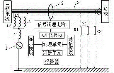
[0024] Such as figure 1 As shown, a downhole power cable insulation monitoring device includes a low-frequency voltage source 1, first to fourth inductors, a Hall current sensor 2, a signal conditioning circuit, an A / D converter, a processing module, a display module, an alarm and The communication module, the processing module includes a processing unit and a judgment unit; the signal conditioning circuit includes a trap circuit, a filter circuit, an amplification circuit and a rectification circuit connected in sequence; wherein,

[0025] The low-frequency voltage source is connected to one end of the first inductance, the other end of the first inductance is respectively connected to one end of the second to fourth inductances, and the other ends of the second to fourth inductances are respectively connected to the three-phase wires in the cable...


PUM

PropertyMeasurementUnit
Frequencyaaaaaaaaaa

Abstract

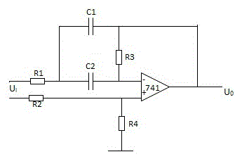
The invention discloses a downhole power cable insulation monitoring device comprising a low-frequency voltage source, first to fourth inductors, a Hall current sensor, a signal conditioning circuit, an A / D converter, a processing module, a display module, an alarm, and a communication module. The processing module comprises a processing unit and a determining unit. The signal conditioning circuit comprises a wave trap circuit, a filtering circuit, an amplification circuit, and a rectification circuit. The wave trap circuit comprises first to fourth resistors, a first capacitor, a second capacitor, and an operational amplifier. The downhole power cable insulation monitoring device may online monitor the insulation state of a cable in real time, improves coal mine power supply continuity, reliability and security, achieves high sensitivity and low errors, and timely notifies downhole and ground workers for carrying out handling so as to guarantee operation safety and prevent economic losses.

Description

technical field [0001] The invention relates to the technical field of electric equipment insulation monitoring, in particular to an insulation monitoring device for underground power cables. Background technique [0002] With the rapid development of new energy industries such as wind power generation and photovoltaic power generation, the number and length of power cables are also increasing rapidly. Power cables are widely used in industrial and mining enterprises, railways and urban power supply departments, among which coal mines are the largest users of cables. Due to the special environment underground in coal mines, during the operation of cables, due to mechanical damage, overvoltage and gradual infiltration of water, the long-term electric field Under the action, partial discharge will occur inside the cable, causing aging and insulation resistance drop. If the fault line is not determined and cut off in time, there will be a major safety hazard in the power supply...

Claims


Application Information

Patent Timeline
IPC IPC(8): G01R31/08
Inventor 宋剑
Owner 苏州市新瑞奇节电科技有限公司
Learn More