An air-proof burning energy-saving stove

A technology for air-proof burning and stoves, applied in the field of stoves, can solve the problems of reducing failure rate, false alarm rate and high failure rate, increasing kitchen temperature, etc., to achieve the effects of improving efficiency, stable and continuous work, and preventing false alarms

Active Publication Date: 2017-09-29
ANHUI HANSUM INSTR EQUIP
View PDF1 Cites 0 Cited by
  • Summary
  • Abstract
  • Description
  • Claims
  • Application Information

AI Technical Summary

Problems solved by technology

[0002] For the cooking stoves used in the catering industry, although the cooking stoves can be turned off during the intervals before and after cooking, such as side dishes, plate loading, and pot washing, etc., when no fire is needed, but during the peak period of passenger flow, the chefs are too busy. There is no time to turn off the fire. In addition, once the stove is turned off, it needs to be re-ignited and turned on to adjust the fire. For the catering work that races against time, the efficiency of serving food will be reduced. Therefore, the stove is often left to burn in vain, which wastes fuel. raised the temperature in the kitchen
At present, although there are many anti-air burning technologies in China, such as the use of infrared sensor switches to automatically ignite or turn off the stove, but because the kitchen environment has high humidity and heavy oil pollution, the false alarm rate and failure rate are high, so that the stove The situation of burning in vain has not been effectively resolved, resulting in fuel waste and increased catering operating costs
[0003] Chinese patent document CN 201680442U discloses a cooker with a pedal control device, which controls the switch of the solenoid valve through the pedal, which reduces the failure rate of the induction system caused by the poor kitchen environment; Busy, basically no time to perform operations that require the cooperation of other limbs, so the practicality of this device is not high, and its theoretical effect cannot be achieved to achieve the purpose of energy saving

Method used


Image

  • An air-proof burning energy-saving stove
  • An air-proof burning energy-saving stove
  • An air-proof burning energy-saving stove

Examples


Embodiment Construction

[0053] In order to make the object, technical solution and advantages of the present invention clearer, the present invention will be further described in detail below in conjunction with examples.

[0054] 1. Wok induction device

[0055] 1.1 Sensing device for wok cooking station

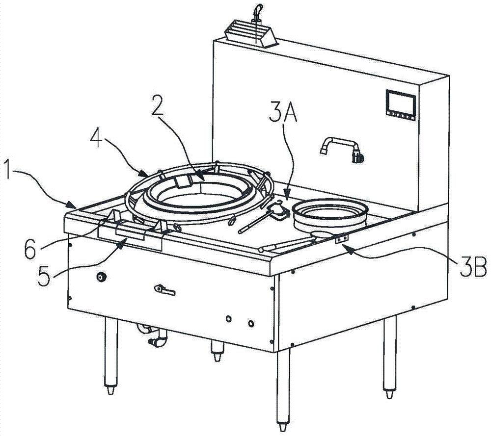
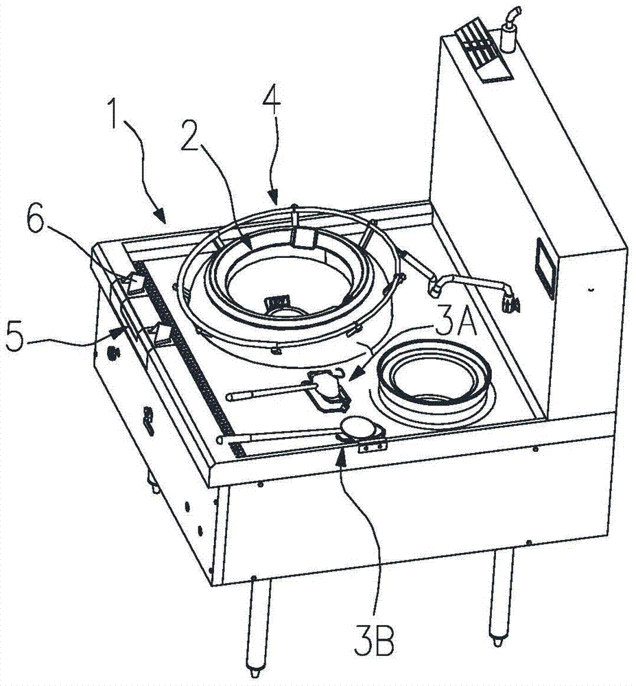
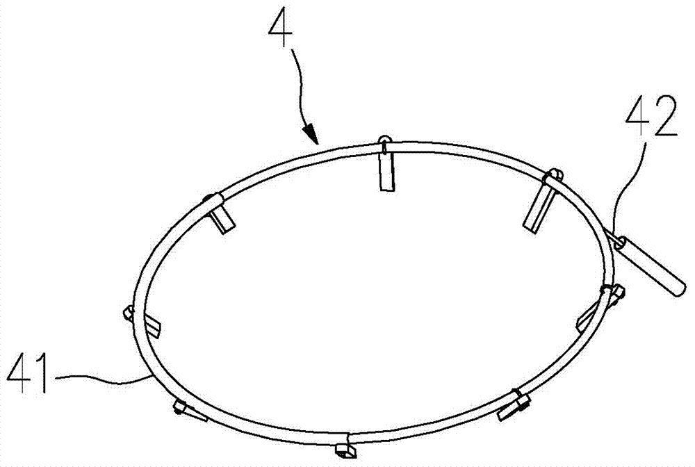
[0056] Such as figure 2 As shown, the support ring 4 suspended on the furnace ring 2 is set as a hollow ring body that can be embedded with the first non-contact electromagnetic induction sensor A42; the support ring 4 is made of polytetrafluoroethylene, and the support ring 4 is made of polytetrafluoroethylene. The side of the ring 4 facing the front edge is also sheathed with a shielding component 41 for shielding electromagnetic interference, and the shielding component 41 is a curved metal pipe section sleeved on the side of the support ring facing the front edge.

[0057] Such as image 3 , 4 As shown in . , the first non-contact electromagnetic induction sensor B22 is arranged in the f...


PUM


Abstract

The invention relates to an anti-vacant-combustion energy-saving stove. The anti-vacant-combustion energy-saving stove comprises a frying pan induction device used for inducing a frying pan and a frying spoon induction device used for inducing a frying spoon. Due to the fact that the frying pan induction device and the frying spoon induction device are both arranged on the anti-vacant-combustion energy-saving stove, a rigorous anti-vacant-combustion system is formed; the frying pan and the frying spoon are both taken into consideration of the anti-vacant-combustion system, and meanwhile the working habits of different chefs are taken into consideration, so that the purpose of vacant-combustion prevention can be achieved timely on the stove for any chef and under any condition, and therefore the anti-vacant-combustion efficiency of the stove is greatly improved. The anti-vacant-combustion energy-saving stove is simple in structure, convenient and fast to operate, low in failure rate and stable in operation, and the anti-vacant-combustion effect is improved effectively.

Description

technical field [0001] The invention belongs to the technical field of stoves, and in particular relates to an air-proof and energy-saving stove. Background technique [0002] For the cooking stoves used in the catering industry, although the cooking stoves can be turned off during the intervals before and after cooking, such as side dishes, plate loading, and pot washing, etc., when no fire is needed, but during the peak period of passenger flow, the chefs are too busy. There is no time to turn off the fire. In addition, once the stove is turned off, it needs to be re-ignited and turned on to adjust the fire. For the catering work that races against time, the efficiency of serving food will be reduced. Therefore, the stove is often left to burn in vain, which wastes fuel. The temperature in the kitchen was raised again. At present, although there are many anti-air burning technologies in China, such as the use of infrared sensor switches to automatically ignite or turn off...

Claims


Application Information

Patent Timeline
Patent Type & Authority Patents(China)
IPC IPC(8): F24C3/12
CPCY02B40/00
Inventor 夏光超葛铜川李大发姚立茹
Owner ANHUI HANSUM INSTR EQUIP
Why Eureka
Try Eureka