
Parking locking mechanism for automatic transmissions

A technology for automatic transmissions and parking locks, applied in the mechanical field, can solve the problems of difficult manufacturing and processing of parking push rods, unguaranteed precision, and high manufacturing costs, and achieve smooth changes in shifting force, simple structure of parts, and reduced processing difficulty Effect

Inactive Publication Date: 2015-12-02
CHONGQING CHANGAN AUTOMOBILE CO LTD
View PDF6 Cites 17 Cited by
  • Summary
  • Abstract
  • Description
  • Claims
  • Application Information

AI Technical Summary

Problems solved by technology

[0004] At present, most parking lock mechanisms for automatic transmissions have the problems of complex structure, difficult layout and high cost
like figure 1 As shown, first of all, the distance between the parking actuator of the parking mechanism - the parking slider (c) and the shift shaft (a) is relatively long, resulting in not only a long parking push rod (b), but also many bends (In order to avoid interference with other parts in the box), the manufacturing and processing of the parking push rod (b) is very difficult and the accuracy cannot be guaranteed, so it is difficult to arrange; secondly, its pawl pushing mechanism includes the parking slider (c) and guide The sleeve (d), the sleeve (d) must not only ensure the smooth sliding of the parking slider (c) but also limit it, so the structure of the sleeve (d) is more complicated; finally the parking slider (c) ) Because the angle of the inclined plane directly affects the magnitude of the shifting force, it requires high precision, so its manufacturing cost is relatively high

Method used


Image

  • Parking locking mechanism for automatic transmissions
  • Parking locking mechanism for automatic transmissions
  • Parking locking mechanism for automatic transmissions

Examples


Embodiment Construction

[0025] The following will clearly and completely describe the technical solutions in the embodiments of the present invention with reference to the accompanying drawings in the embodiments of the present invention. Obviously, the described embodiments are only part of the embodiments of the present invention, not all of them. Based on the embodiments of the present invention, all other embodiments obtained by persons of ordinary skill in the art without creative efforts fall within the protection scope of the present invention.

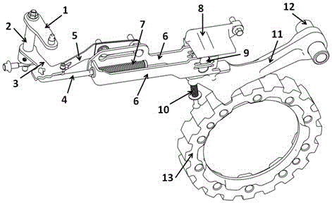
[0026] Such as figure 2 As shown, the parking lock mechanism proposed by the present invention includes a shift rocker 1 operated by a shifter, a shift shaft 2, a shift arm 3 that accepts the action of the shift rocker 1, and a gear shift arm 3 that engages with the shift arm recess. The brake spring plate 5 to realize the gear locking in the groove area, the parking push rod 4, the parking spring 7, the guide plate 8, the roller frame 6, the roller ...


PUM


Abstract

The invention provides a parking locking mechanism for automatic transmissions. The parking locking mechanism comprises a gearshift rotary arm, a gearshift shaft, a gearshift rocker arm, a transfer assembly, a parking pawl and a parking gear, wherein the transfer assembly comprises a parking push rod, a parking spring, a rolling wheel frame and a rolling wheel; the rolling wheel is matched with the parking pawl, and acts on a pawl rolling path of the parking pawl; and the parking pawl is matched with the parking gear. The gearshift rocker arm of the parking locking mechanism drives the gearshift rotary arm to carry out a gearshift action through the rotation of the gearshift shaft, the gearshift rotary arm is connected with the transfer assembly and transfers a gearshift power to the parking pawl, and the parking pawl is matched with the parking gear to realize locking and unlocking; and the parking locking mechanism is simple in structure, capable of being adjusted in size and position according to different use needs, easy to use in the different automatic transmissions, and high in universalization degree.

Description

technical field [0001] The invention belongs to the technical field of machinery and relates to a parking locking mechanism of an automatic transmission of an automobile. Background technique [0002] The motor vehicle parking lock mechanism is used to lock the motor vehicle when the vehicle is stationary. It is a common security system to ensure that there will be no slippage or slope after parking by locking the vehicle drive shaft in the direction of rotation. device. Parking lock mechanisms are especially suitable for use in motor vehicles with automatic transmissions and in hybrid or electric vehicles. [0003] When the parking lock brake is applied, the components involved are subjected to high loads. If the vehicle is still running when the parking lock mechanism brakes, a huge impact will be transmitted to the parking lock mechanism through the vehicle drive shaft, so the components of the parking lock mechanism must have sufficient reliability. [0004] At presen...

Claims


Application Information

Patent Timeline
IPC IPC(8): F16H63/34
CPCF16H63/3433F16H2306/00
Inventor 刘诗王鑫夏灵曾俊
Owner CHONGQING CHANGAN AUTOMOBILE CO LTD
Learn More