
Biological kinetic energy dragging type power generation system

A power generation system, drag-type technology, applied in the direction of generating mechanical power by physical force, mechanisms for generating mechanical power, machines/engines, etc., to achieve the effect of improving the effective effect, increasing the supporting strength, and satisfying the mechanical strength

Active Publication Date: 2015-12-02
JIANGSU ZHONGYUN WIND POWER SCIENCE & TECHNOLOGY CO LTD
View PDF13 Cites 1 Cited by
  • Summary
  • Abstract
  • Description
  • Claims
  • Application Information

AI Technical Summary

Problems solved by technology

[0004] In view of the above-mentioned existing problems, the applicant has carried out research and improvement, and provides a biokinetic drag-type power generation system. The structure of the present invention effectively solves the effective coupling between the central axis of the animal power generation system and the generator. It has high power, large The structure not only realizes the problem of multi-coaxial kinetic energy adjustment and balance, but also is suitable for large-scale network construction, which can provide high-quality and low-cost power supply for tens of millions of users

Method used


Image

  • Biological kinetic energy dragging type power generation system
  • Biological kinetic energy dragging type power generation system
  • Biological kinetic energy dragging type power generation system

Examples


Embodiment Construction

[0045] The specific embodiments of the present invention will be described below in conjunction with the drawings.

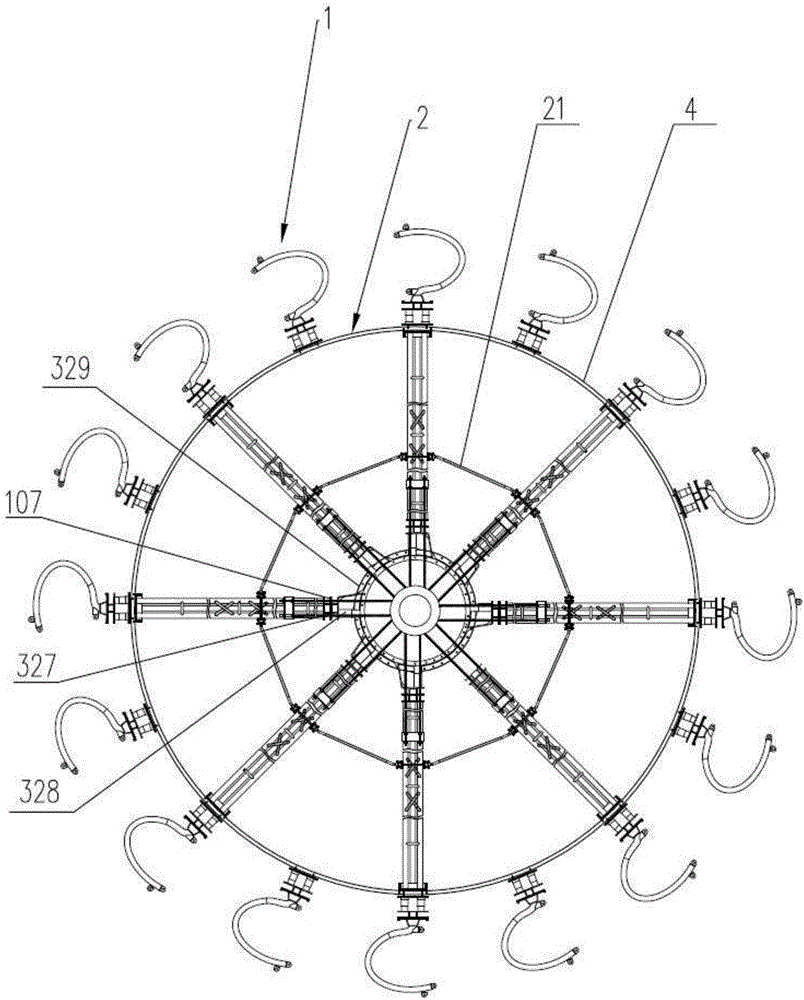
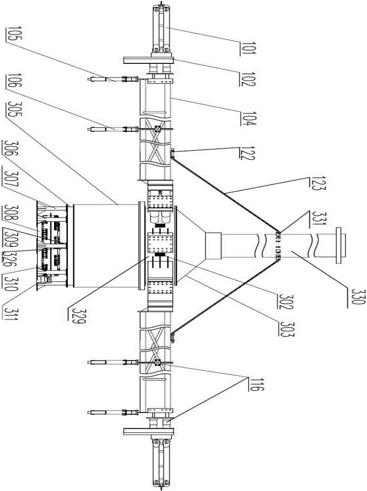
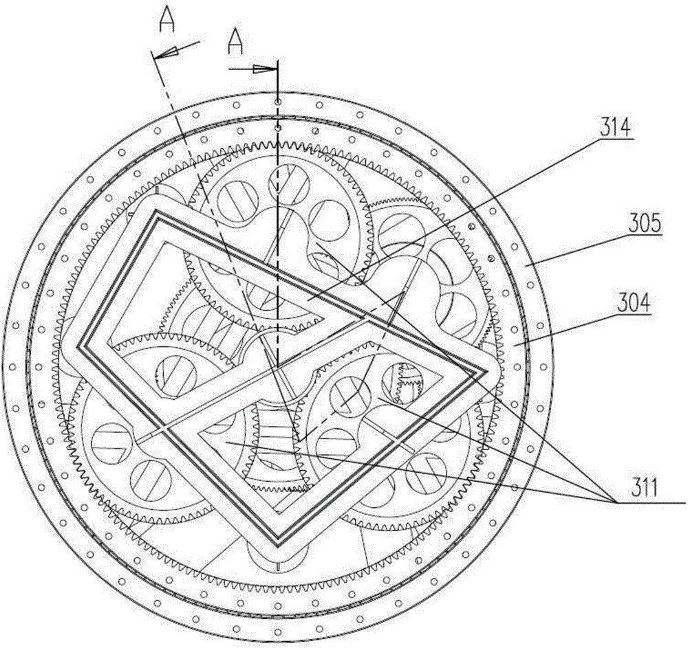
[0046] Such as figure 1 As shown, the biological kinetic energy drag-type power generation system includes a speed-increasing rotor system 3 and a generator system. The outer circumference of the speed-increasing rotor system 3 and the rotor system are evenly connected with a plurality of force transmission arm systems 1 along the circumferential direction. The rotor system of the system 3 drives each of the force transmission arm systems 1 to rotate in the circumferential direction, so that the biological kinetic energy is converted from the speed-increasing rotor system 3 through the generator system to electrical output. Such as figure 1 , figure 2 As shown, a plurality of balance systems 2 are connected between each force transmission arm system 1, and the balance system 2 includes an inner balance tie rod 21, and the inner balance tie rods 21 are all connected...


PUM


Abstract

The invention relates to a biological kinetic energy dragging type power generation system which comprises a speed-increasing rotor system. The periphery of the speed-increasing rotor system is evenly connected with multiple force transmission arm systems in the peripheral direction, and biological kinetic energy drives all the force transmission arm systems to rotate in the peripheral direction by taking the speed-increasing rotor system as a circle center, so that the biological kinetic energy is converted into electric energy through an electric generator by the speed-increasing rotor system to be output. According to the biological kinetic energy dragging type power generation system, the structure is simple, use is convenient, and low-speed biological stepping kinetic energy is converted into high-low kinetic energy needed by the electric generator through the force transmission arm systems and the speed-increasing rotor system by utilizing the biological kinetic energy; according to the force transmission arm systems, the supporting strength of force arm rods is improved through supporting rod assemblies, and meanwhile smooth transition of the force arm rods in dynamic operation is achieved through a vibration avoiding system and a pulley mechanism. The biological kinetic energy dragging type power generation system has the high power, is of a large structure, is suitable for large-scale networking station building and can supply high-quality and low-cost electric power supply to ten millions of users.

Description

Technical field [0001] The present invention relates to power generation equipment, and in particular to a towed power generation system that uses organisms (livestock or humans) as power energy. Background technique [0002] As mankind enters the 21st century, the development of society is accelerating. Electric energy is widely used in various fields such as power, lighting, metallurgy, chemistry, textiles, and communications. It is the main driving force for the development of science and technology and the leap of the national economy. The main source of original electricity is to obtain clean electricity from renewable energy sources such as nuclear energy, biomass energy, solar energy, wind energy, and hydropower. With the increasing shortage of fossil energy and the pollution caused by humans to the natural environment, the above-mentioned renewable energy Due to the limitations of geography, weather and investment conditions, it cannot meet the power demand in areas with ...

Claims


Application Information

Patent Timeline
IPC IPC(8): F03G5/04
Inventor 李勇强谢玉琪姚伯龙汪旭吴飞
Owner JIANGSU ZHONGYUN WIND POWER SCIENCE & TECHNOLOGY CO LTD
Learn More