A fully embedded installation and erection device on the side of a cantilever beam

A pre-embedded device and cantilever frame technology, which is applied to the accessories of scaffolding, buildings, and housing structure supports, can solve problems such as delaying construction progress, installation fatigue, and strength discounts, so as to ensure construction quality, smooth follow-up construction, and reduce The effect of lost time

Active Publication Date: 2018-08-03
HUNAN ZHENG WEI CONSTR SCI & TECH
View PDF8 Cites 3 Cited by
  • Summary
  • Abstract
  • Description
  • Claims
  • Application Information

AI Technical Summary

Problems solved by technology

[0002] When traditional cantilevered I-beams are installed, such as figure 1 As shown, the I-beam b is laid on the floor a through the shear wall, and then fixed to the floor with the steel bar c. Because it is too heavy, the installation is extremely tiring, cumbersome and time-consuming. When it passes through the shear wall, it will be damaged. The cross-section of the wall leads to a discount in the design strength and increases the difficulty of carpentry molding
It is even more difficult to dismantle it. Sometimes it takes two people half a day to remove an I-shaped beam that runs through the shear wall. If it cannot be hoisted to a position that cannot be hoisted, safety is a big hidden danger
After the demolition, the wall will be riddled with holes everywhere, which is shocking and greatly reduces the construction quality (not to mention that the strength of the hole added later will be discounted, but it is undoubtedly the biggest source of leakage. I-beams are indoors. After the fixed position is removed, it will also cause leakage in the later stage), and it also greatly delays the construction progress

Method used


Image

  • A fully embedded installation and erection device on the side of a cantilever beam
  • A fully embedded installation and erection device on the side of a cantilever beam
  • A fully embedded installation and erection device on the side of a cantilever beam

Examples


Embodiment Construction

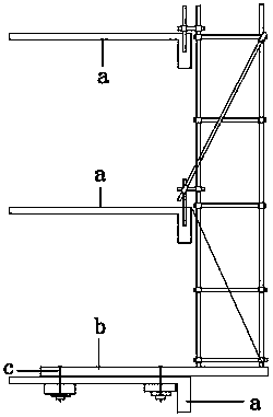
[0029] In the existing technology, such as Figure 10 , 11 As shown, according to the "Steel Steel Scaffolding Specification", the maximum scaffolding height is 18m plus 1.5m railing, a total of 19.5m; the inner pole 17 is 0.3m away from the outer wall of the building structure 15, and the horizontal distance between the inner pole 17 and the outer pole 16 is 0.9m, the longitudinal distance is 1.5m, and the step distance is 1.8m. A horizontal sweeping rod 24 and a vertical sweeping rod 25 are arranged at a height of 200 mm on the top surface of the I-beam 1 . The horizontal sweeping bar 24 is fixed on the bottom of the vertical bar with a fastener, and then on the horizontal sweeping bar 24, the longitudinal sweeping bar 25 is fixed on the bottom of the vertical bar with a fastener to ensure the overall stability of the fastener steel pipe scaffold. The outer facade of the fastener steel pipe scaffold is covered with scissor braces 23 with a span of 4 and 6m, and between the...


PUM


Abstract

The invention discloses a fully pre-embedded installation and erection device on the side of a cantilevered girder, which includes an I-shaped steel and a pre-embedded device. The buried device I is fixedly connected. The lower part of the I-beam away from the concrete wall is provided with a support point fixing device I that can freely adjust the angle. The support point fixing device I is connected to the support point fixing device II set on the concrete wall through the supporting steel pipe. Connection, the support point fixing device II is connected with the pre-embedded device II installed in the concrete wall through bolts, the two ends of the supporting steel pipe are provided with trapezoidal threads, and the middle and upper parts are provided with positive and negative trapezoidal tooth adjustment screws, the support point fixing device I, the support The point fixing devices II are respectively provided with trapezoidal screw rods that can adjust the angle freely, and the trapezoidal screw rods are respectively connected with the internal threads at both ends of the supporting steel pipe. The structure of the invention is very simple, the installation and removal are very convenient, the material is greatly saved, and the progress is improved.

Description

technical field [0001] The invention mainly relates to the field of building construction auxiliary equipment, and specifically discloses a fully pre-embedded installation and erection device on the side of a cantilevered girder. Background technique [0002] When traditional cantilevered I-beams are installed, such as figure 1 As shown, the I-beam b is laid on the floor a through the shear wall, and then fixed to the floor with the steel bar c. Because it is too heavy, the installation is extremely tiring, cumbersome and time-consuming. When it passes through the shear wall, it will be damaged. The cross-section of the wall leads to a discount in the design strength and increases the difficulty of carpentry molding. It is even more difficult to dismantle it. Sometimes it takes two people half a day to remove an I-beam that runs through the shear wall. If it cannot be hoisted, it will be a big hidden danger to safety. After the demolition, the wall will be riddled with hol...

Claims


Application Information

Patent Timeline
Patent Type & Authority Patents(China)
IPC IPC(8): E04G5/04
Inventor 赵拯卫叶柏龙苏灿赵梓元蒋青青蒋竞舶蒋金津童玲玲刘应松
Owner HUNAN ZHENG WEI CONSTR SCI & TECH
Why Eureka
Try Eureka