Directional feeding device of needle seats
A needle seat and positioning groove technology, applied in the directions of transportation and packaging, conveyor objects, etc., can solve the problems of inability to achieve directional feeding of double-blade needle seats, pollution of medical accessories, slow speed, etc., to increase positioning effect and stability. Good, high-yield effects
- Summary
- Abstract
- Description
- Claims
- Application Information
AI Technical Summary
Problems solved by technology
Method used
Image
Examples
Embodiment 1
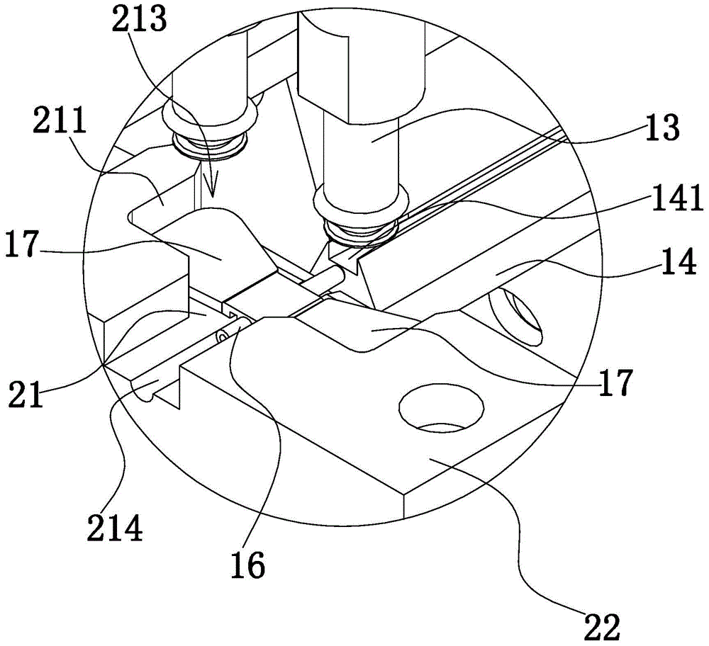
[0039] The directional feeding device of the needle holder is mainly used for the reversing of the double blade 17 needle holder. Such as Figure 9 As shown, the double blade 17 needle hub includes a tubular needle handle 16 and two blades 17 connected to the outer wall of the needle handle 16 , and there are two strip-shaped opening grooves 161 on the needle handle 16 .
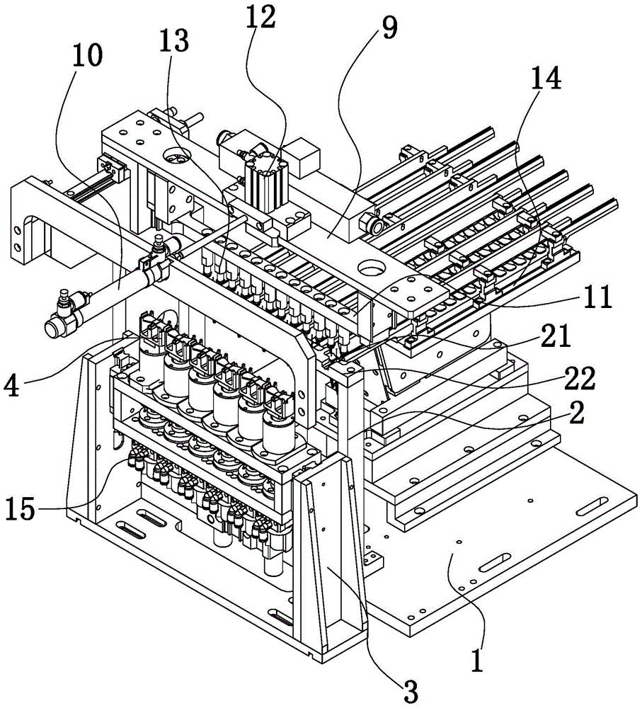
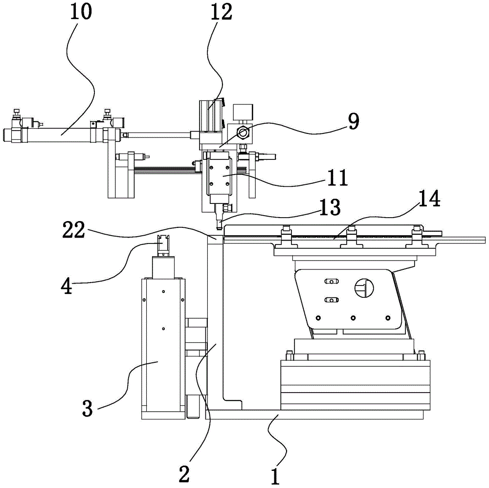
[0040] Such as figure 1 and figure 2 As shown, the directional feeding device of the needle seat includes a frame 1, on which a detection seat 2, a reversing seat 3 and a feeding platform 14 are fixed, and the top of the detection seat 2 has a strip-shaped detection plate 22. The detection board 22 is arranged horizontally, and the upper surface of the detection board 22 is provided with a plurality of positioning grooves 21 , and the positioning grooves 21 are evenly spaced along the length direction of the detection board 22 . A number of parallel feed slots 141 are arranged side by side on the feed pl...
Embodiment 2
[0048] The structure and principle of this embodiment are basically the same as that of the first embodiment, except that the detection structure includes a camera mounted on the frame 1 capable of taking pictures of the needle seat in the positioning groove 21 and a controller connected to the camera. A camera is arranged above each positioning groove 21, and the camera acquires an image of the orientation of the needle holder in the positioning groove 21 and sends it to the controller, and the controller judges the orientation of the needle holder.
Embodiment 3
[0050] The structure and principle of this embodiment are basically the same as that of Embodiment 1 or Embodiment 2. The difference is that the rotating base 4 is block-shaped, the bottom of the rotating base 4 is connected with the driving part, and the positioning mechanism is included on the upper part of the rotating base 4. The surface is provided with a fixed groove, and the bottom of the fixed groove is provided with an air suction hole, and the air suction hole is connected with an air suction pump. The needle seat is prevented from being in the fixed groove, and the suction pump generates negative pressure in the suction hole, which makes the needle seat firmly adsorbed in the positioning groove 21, and prevents the needle seat from being caught by the rotating seat 4 during rotation. throw out.
PUM
 Abstract
Description
Claims
Application Information
 - R&D
- Intellectual Property
- Life Sciences
- Materials
- Tech Scout
- Unparalleled Data Quality
- Higher Quality Content
- 60% Fewer Hallucinations
Browse by: Latest US Patents, China's latest patents, Technical Efficacy Thesaurus, Application Domain, Technology Topic, Popular Technical Reports.
© 2025 PatSnap. All rights reserved.Legal|Privacy policy|Modern Slavery Act Transparency Statement|Sitemap|About US| Contact US: help@patsnap.com


