
Variable damping force damper

A damping force and shock absorber technology, which is applied in the direction of shock absorbers, springs/shock absorbers, shock absorbers, etc., can solve problems such as reduced responsiveness, weak magnetic force, and reduced vehicle comfort, and achieve staged changes inhibitory effect

Active Publication Date: 2015-11-25
HONDA MOTOR CO LTD
View PDF6 Cites 1 Cited by
  • Summary
  • Abstract
  • Description
  • Claims
  • Application Information

AI Technical Summary

Problems solved by technology

[0010] That is, if the distance between the piston rod and the valve hole is short, even if the magnetic force generated by supplying electric power to the electromagnetic solenoid is weak, a large pressure is required to push the pressure side check valve open. Responsiveness to changes in the pressure of hydraulic oil flowing through the valve hole decreases
In this way, if the responsiveness is lowered, the adjustment of the damping force cannot be performed quickly, which causes a problem that the comfort of the vehicle equipped with the hydraulic shock absorber is lowered.

Method used


Image

  • Variable damping force damper
  • Variable damping force damper
  • Variable damping force damper

Examples


Embodiment Construction

[0032] Hereinafter, embodiments of the present invention will be described in detail with reference to the drawings as appropriate.

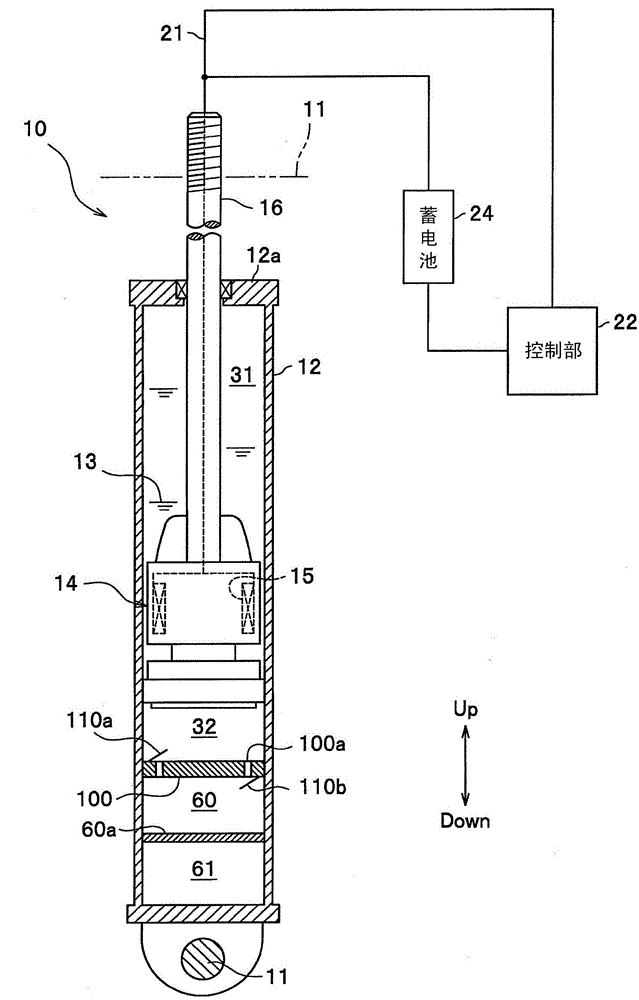
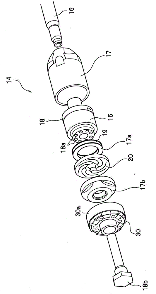
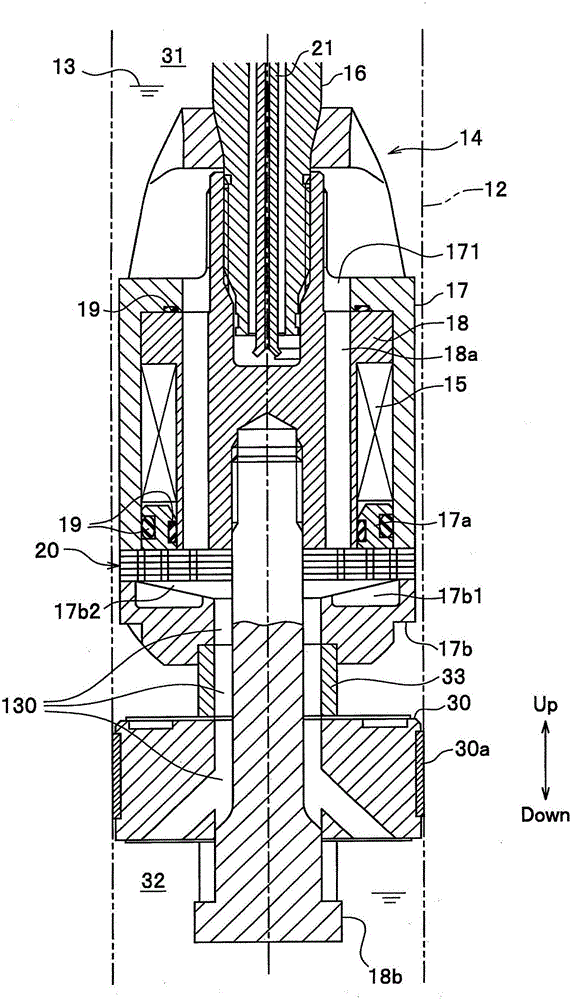
[0033] figure 1 is the structural diagram of the damping force variable shock absorber, figure 2 is a perspective view showing the structure of the piston assembly, image 3 is a cross-sectional view of the piston assembly.

[0034] Such as Figure 1~3 As shown, the damping force variable shock absorber 10 of this embodiment is a shock absorber that actively changes the damping force to absorb vibrations generated in the vehicle 11 .

[0035] The variable damping force damper 10 includes: a cylindrical hydraulic cylinder 12; a piston assembly 14 slidably accommodated in the hydraulic cylinder 12; The piston rod 16.

[0036] In this embodiment, the vertical direction (Up, Down) of the damping force variable damper 10 is set with the side of the upper end portion 12a protruding from the piston rod 16 being upward (Up).

[0037] In addition,...


PUM


Abstract

A variable damping force damper is configured so that a piston assembly, which is housed within a cylinder in a slidable manner and which divides the cylinder into an upper hydraulic chamber and a lower hydraulic chamber, is configured so as to include: a piston body (18) which has valve holes (18a) through which hydraulic oil flows between the upper hydraulic chamber and the lower hydraulic chamber; and a laminated valve (20) which opens and closes the valve holes (18a). The variable damping force damper is characterized in that the laminated valve (20) has an outer peripheral section (20b) and opening / closing sections (20a), the opening / closing sections (20a) being extended from the outer peripheral section (20b) toward the center of the laminated valve (20) and opening and closing the valve holes (18a), the opening / closing sections (20a) being each configured in such a manner that the distance (L1) measured from the point (P1) of application, to which the pressure of the hydraulic oil flowing through the valve holes (18a) is applied, to the outer peripheral section (20b) measured along the opening / closing section (20a) is greater than a distance (L2) corresponding to the distance from the point (P1) of application to the outer peripheral section (20b).

Description

technical field [0001] The invention relates to a damping force variable shock absorber. Background technique [0002] For example, Patent Document 1 describes a hydraulic shock absorber (variable damping force shock absorber) that is connected to a piston (piston assembly) that slides in a hydraulic cylinder through a pressure side check valve (opening and closing unit). The formed valve hole is opened and closed to adjust the damping force. [0003] The pressure-side check valve adjusts the strength of opening and closing by adjusting the magnetic force generated when electric power is supplied to the electromagnetic solenoid, thereby adjusting the damping force. [0004] prior art literature [0005] patent documents [0006] Patent Document 1: Japanese Patent Publication No. 1-47323 [0007] Summary of the invention [0008] The problem to be solved by the invention [0009] The pressure-side check valve of the hydraulic shock absorber described in Patent Document ...

Claims


Application Information

Patent Timeline
Patent Type & Authority Applications(China)
IPC IPC(8): F16F9/50F16F9/34
CPCF16F9/464F16F9/3484
Inventor 中岛清志岛田和彦大森贵之尾上良雄小川和男
Owner HONDA MOTOR CO LTD
Learn More