Turbo machine combustion assembly comprising an improved fuel supply circuit

A fuel supply and supply circuit technology, applied in the fuel control of turbine/propulsion device, gas turbine device, turbine/propulsion fuel delivery system, etc., can solve the problem of high production cost and achieve the effect of maintenance life

Active Publication Date: 2015-11-25
TURBOMECA SA
View PDF4 Cites 4 Cited by
  • Summary
  • Abstract
  • Description
  • Claims
  • Application Information

AI Technical Summary

Problems solved by technology

[0019] As a result, the supply circuit is a complex assembly with high production costs due to its large number of components

Method used


Image

  • Turbo machine combustion assembly comprising an improved fuel supply circuit
  • Turbo machine combustion assembly comprising an improved fuel supply circuit
  • Turbo machine combustion assembly comprising an improved fuel supply circuit

Examples


Embodiment Construction

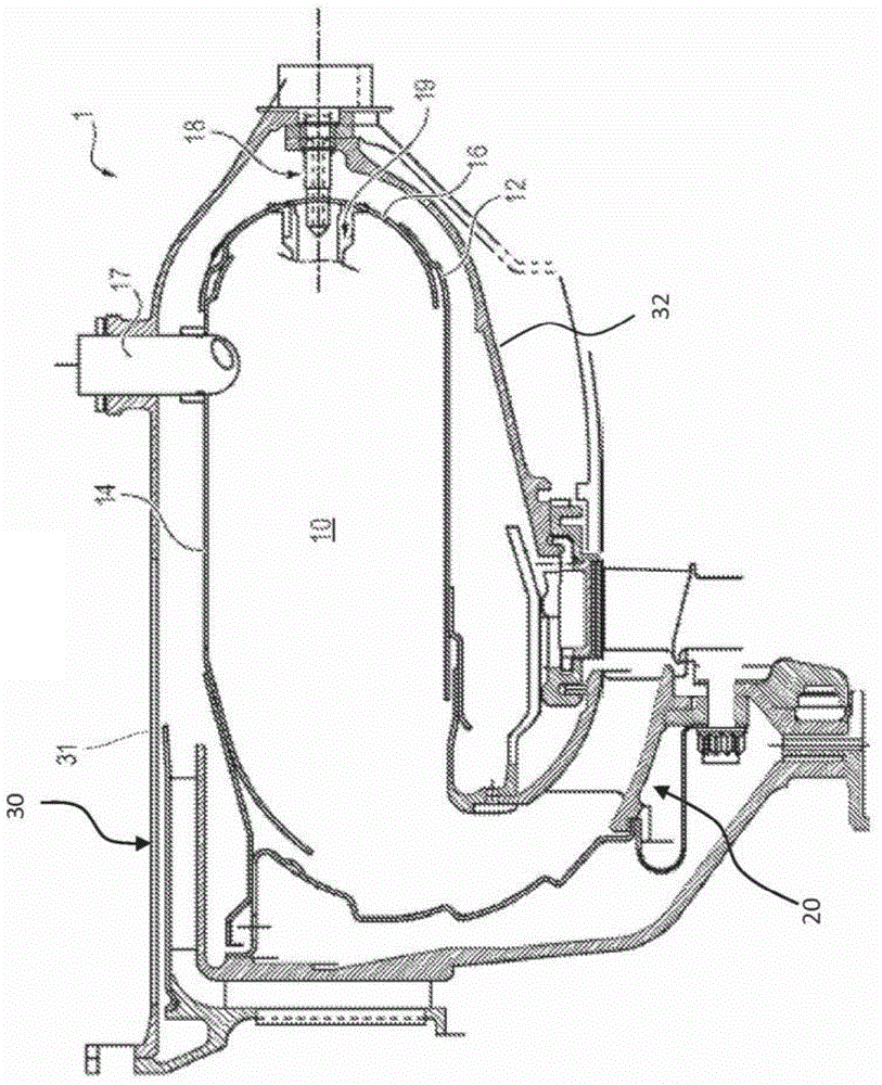
[0058] Reference Figure 3a with Figure 3b , Represents the turbine combustion assembly 1, which includes a combustion chamber 10 and a casing 30 (in Figure 3b Indicated in), the combustion chamber 10 is defined by two axisymmetric outer walls 14 and an inner wall 12, and the outer wall 14 and the inner wall 12 extend nestingly with each other and are connected by an annular combustion chamber end wall 16.

[0059] The housing also includes an outer wall 31 (in Figure 3b Middle) and inner wall (not in Figure 3b Indicated in), the inner wall 12 and the outer wall 14 of the combustion chamber are fastened to the outer wall 31 and the inner wall respectively.

[0060] The turbine 1 also includes a plurality of fuel injectors, including at least one starter injector 17 (preferably, at least two starter injectors 17), and a plurality of main injectors 18 (preferably, at least three main injectors 18), For example, eight main injectors.

[0061] The ignition system includes at least on...


PUM


Abstract

Turbo machine combustion assembly (1) comprising a combustion chamber (10), at least one starting injector (17), a plurality of main injectors (18) distributed at constant angular intervals around the circumference of the combustion chamber, each starting injector being positioned between two consecutive main injectors, equal distances therefrom, and a fuel supply circuit (40) supplying fuel to the injectors, in which assembly the combustion chamber is delimited by two axisymmetric walls - an external wall (14) and an internal wall (12) - which are connected by an annular chamber end wall (16), the fuel supply circuit being designed to supply at least one starting injector continuously, each continuously-supplied starting injector being oriented toward the chamber end wall and dimensioned to spread a spray (F) of fuel between 120° and 180° wide, and the flow rate of fuel injected by the main injectors (18') between which the starting injectors are positioned being reduced by comparison with the flow rate injected by the other main injectors (18).

Description

Technical field [0001] The present invention relates to the field of turbines, and more particularly, to the field of turbine combustion assemblies, which include a combustion chamber and a plurality of injectors dedicated to starting and supplying fuel to the combustion chamber. Background technique [0002] Reference figure 1 The turbine 1 generally includes a combustion chamber 10 and a distributor 20 housed in a casing 30. The combustion chamber is defined by an axisymmetric outer wall 14 and an inner wall 12, which extend in a nesting manner and pass through the end wall of the annular combustion chamber. 16 connections. [0003] The housing also has an inner wall 32 and an outer wall 31, and the inner wall 12 and the outer wall 14 of the combustion chamber are fastened to the inner wall 32 and the outer wall 31, respectively. [0004] The mixture of air and fuel is injected into the combustion chamber through multiple injectors, and the mixture is burned to generate the energy...

Claims


Application Information

Patent Timeline
Patent Type & Authority Applications(China)
IPC IPC(8): F02C7/228F02C9/34F23R3/34
CPCF02C7/228F02C9/34F23R3/32F23R3/343F23R3/50F23R3/34F23R3/42
Inventor 让-皮埃尔·巴德特休伯特·帕斯卡尔·维迪尔
Owner TURBOMECA SA
Why Eureka
Try Eureka