
Laminated glass

A technology for laminated glass and glass substrates, applied in windshields, coatings, glass/slag layered products, etc., can solve the problems of difficulty in having both, reduced light transmittance, and reduced infrared reflectivity, and achieves infrared reflection. Excellent in rate and light transmittance, and the effect of suppressing cracking

Inactive Publication Date: 2015-11-25
KONICA MINOLTA INC
View PDF44 Cites 14 Cited by
  • Summary
  • Abstract
  • Description
  • Claims
  • Application Information

AI Technical Summary

Problems solved by technology

In the conventional laminated glass mentioned above, the light transmittance decreases when the infrared reflectance is increased, and the infrared reflectance decreases when the light transmittance is increased, so there is another problem that it is difficult to combine them.

Method used


Image

  • Laminated glass
  • Laminated glass
  • Laminated glass

Examples


preparation example Construction

[0192] (4-3) Preparation method of coating liquid

[0193] The method of preparing the coating solution for the high refractive index layer and the coating solution for the low refractive index layer is not particularly limited, for example, adding a water-soluble binder resin, metal oxide particles, and other additives added as needed, and stir to mix. At this time, the order of adding the water-soluble binder resin, metal oxide particles, and other additives used as needed is not particularly limited, and each component may be added sequentially while stirring, or may be added and mixed at once while stirring. If necessary, a solvent may be further used to obtain an appropriate viscosity.

[0194]In the present invention, it is preferable to form the high refractive index layer using an aqueous high refractive index layer coating solution prepared by adding and dispersing core-shell particles. In this case, the core / shell particles are preferably prepared by adding to the ...

Embodiment

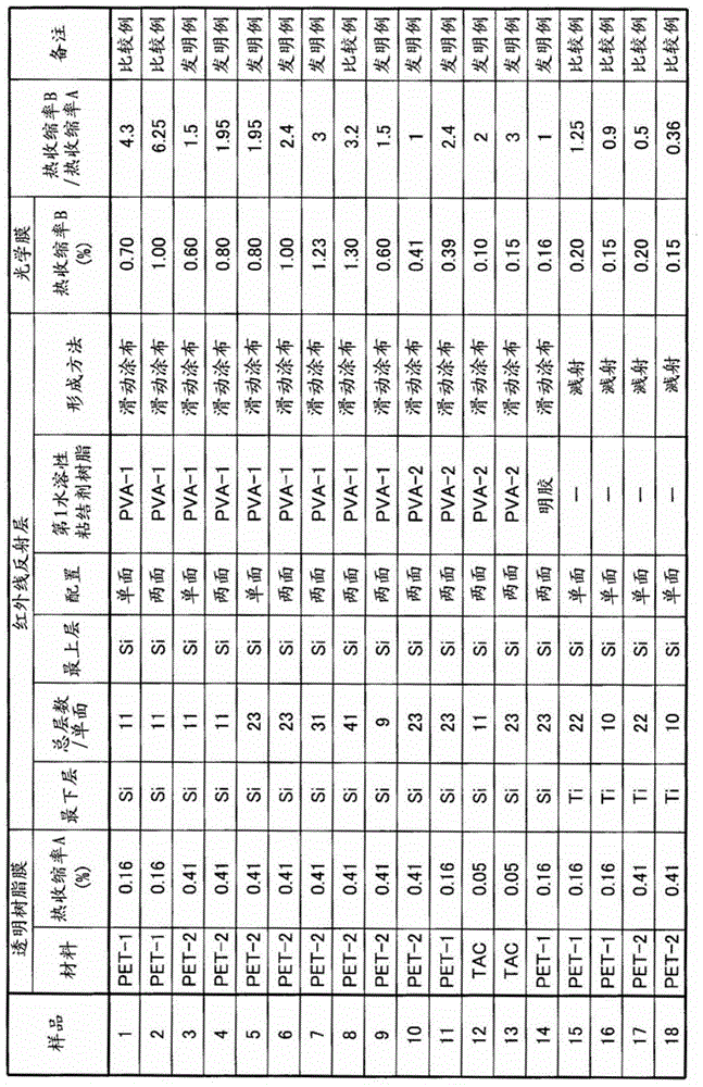
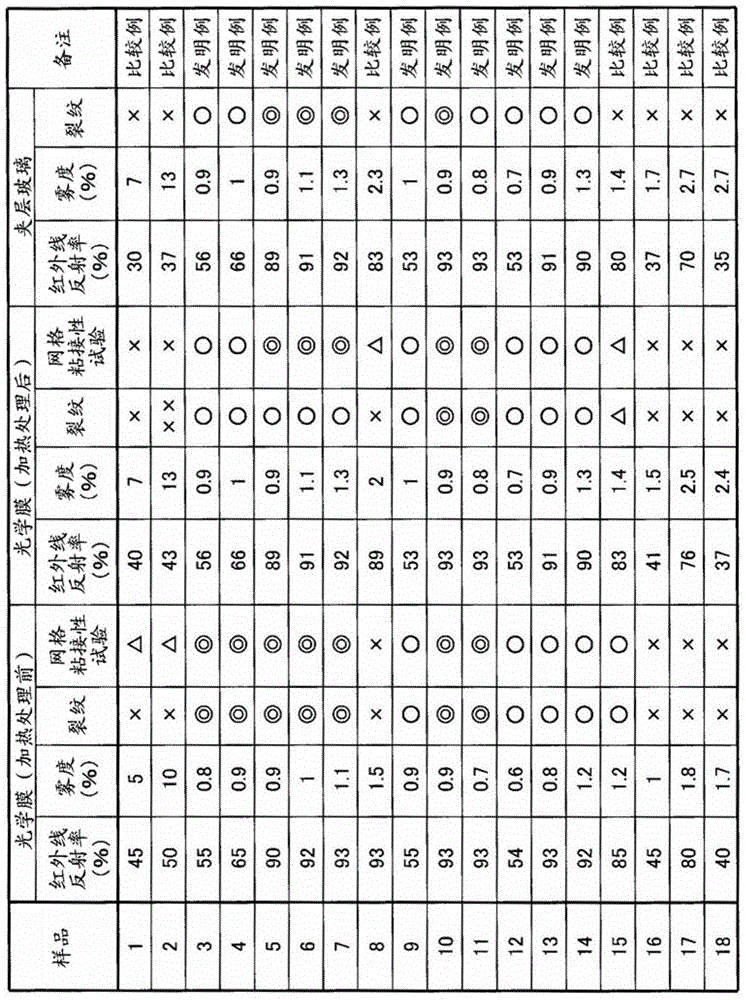
[0284] Hereinafter, although an Example is given and this invention is demonstrated concretely, this invention is not limited to these Examples. In addition, the expression of "%" is used in an Example, Unless otherwise specified, it means "mass %".

[0285] "Making of Laminated Glass 1"

[0286] (Preparation of Coating Liquid L1 for Low Refractive Index Layer)

[0287] First, 680 parts of an aqueous solution of 10% by mass of colloidal silica (manufactured by Nissan Chemical Industry Co., Ltd., SNOWTEX (registered trademark) OXS) as the second metal oxide particles, 4.0% by mass of polyvinyl alcohol (manufactured by Kuraray Co., Ltd. , PVA-103: 300 parts of polymerization degree, 98.5 mol% of saponification degree) aqueous solution, and 150 parts of 3.0 mass % boric acid aqueous solution were mixed and dispersed. Pure water was added to prepare 1000 parts of colloidal silica dispersion liquid L1 as a whole.

[0288] Next, the obtained colloidal silica dispersion L1 was hea...


PUM

PropertyMeasurementUnit
thicknessaaaaaaaaaa
thicknessaaaaaaaaaa
particle sizeaaaaaaaaaa

Abstract

This laminated glass comprises: an optical film having at least one layer of an infrared reflecting layer on a transparent resin film; and a pair of glass substrates that sandwich the optical film. The infrared reflecting layer comprises a high refractive index layer which includes a first water-soluble binder resin and first metal oxide particles and a low refractive index layer which includes a second water-soluble binder resin and second metal oxide particles, the two layers being alternately laminated, and a value obtained by dividing the thermal shrinkage rate of the optical film by the thermal shrinkage rate of the transparent resin film is in the range of 1 to 3.

Description

technical field [0001] The present invention relates to laminated glass. In particular, by specifying the structure of the infrared reflective layer and the relationship between the thermal shrinkage rates of the optical film and the transparent resin film, it is possible to suppress damage to the infrared reflective layer caused by heat treatment during manufacture, and Provided is a laminated glass excellent in infrared reflectivity and light transmittance. Background technique [0002] In recent years, for the purpose of shielding the heat felt by the human skin due to the influence of sunlight entering through the window, and suppressing the operation of the air conditioner in the car to save energy, there are products with high heat insulation or heat radiation on the market. Shielding laminated glass. [0003] Generally, laminated glass is formed by disposing an optical film between a pair of glass substrates. The optical film shields the transmission of heat radiatio...

Claims


Application Information

Patent Timeline
Patent Type & Authority Applications(China)
IPC IPC(8): C03C27/12B60J1/00
CPCB60J3/007B32B17/10036B32B17/10449B32B17/10761C03C3/087C03C17/3681C03C17/42C03C27/06C03C2217/42C03C2217/445C03C2217/475C03C2217/734B32B17/10005B32B2367/00G02B5/0841G02B5/282
Inventor 伊原一仁
Owner KONICA MINOLTA INC
Learn More