
Flexible film solar cell packaging method and solar cell

A technology for solar cells and solar cell sheets, applied in the field of solar cells, can solve the problems of damage, high rigidity and easy breakage of solar cells, and achieve the effects of being convenient to carry and install, broadening the application field, and not easily broken and damaged.

Active Publication Date: 2015-11-25
浙江尚越新能源开发有限公司
View PDF4 Cites 14 Cited by
  • Summary
  • Abstract
  • Description
  • Claims
  • Application Information

AI Technical Summary

Problems solved by technology

[0003] In the prior art, glass-encapsulated solar cells are generally used. This type of encapsulation mainly has the following problems: (1) The thickness of the solar cells obtained after encapsulation is relatively large. On the one hand, it is inconvenient to carry and install; on the other hand, it is difficult to apply It is used in fields with very strict weight requirements; (2) The solar cells obtained after packaging are relatively rigid, and are easily broken and damaged during installation and use

Method used


Image

  • Flexible film solar cell packaging method and solar cell
  • Flexible film solar cell packaging method and solar cell
  • Flexible film solar cell packaging method and solar cell

Examples


Embodiment 2

[0064] S1, the laminator consists of a lower base 8 and an upper machine cover 6 to form a lamination chamber; an air bag 7 is horizontally arranged in the lamination chamber, and the air bag 7 divides the lamination chamber into an upper lamination chamber 9 and a lower lamination chamber 10;

[0065] On the lower base 8 of the laminator, the back sheet 5, the first hot melt adhesive PVB, the solar cell sheet 3, the second hot melt adhesive PVB and the transparent waterproof vapor barrier are laid in sequence from bottom to top. Molecular Thin Film 1;

[0066] S2, closing the upper machine cover 6, at this time, the upper lamination chamber 9 and the lower lamination chamber 10 are both in an atmospheric pressure state;

[0067] The upper lamination chamber 9 and the lower lamination chamber 10 are evacuated to a vacuum state by vacuuming equipment; The temperature value T is 135°C;

[0068] S3, use the inflator to inflate the upper lamination chamber 9 with the first infl...

Embodiment 3

[0073] S1, the laminator consists of a lower base 8 and an upper machine cover 6 to form a lamination chamber; an air bag 7 is horizontally arranged in the lamination chamber, and the air bag 7 divides the lamination chamber into an upper lamination chamber 9 and a lower lamination chamber 10;

[0074] On the lower substrate 8 of the laminator, the back sheet 5, the first hot melt adhesive TPU, the solar cell sheet 3, the second hot melt adhesive TPU and the high transparent waterproof vapor are laid sequentially from bottom to top. Molecular Thin Film 1;

[0075] S2, closing the upper machine cover 6, at this time, the upper lamination chamber 9 and the lower lamination chamber 10 are both in an atmospheric pressure state;

[0076] The upper lamination chamber 9 and the lower lamination chamber 10 are evacuated to a vacuum state by vacuuming equipment; The temperature value T is 151°C;

[0077] S3, use the inflation device to inflate the upper lamination chamber 9 with the...


PUM

PropertyMeasurementUnit
thicknessaaaaaaaaaa
tensile strengthaaaaaaaaaa
thicknessaaaaaaaaaa

Abstract

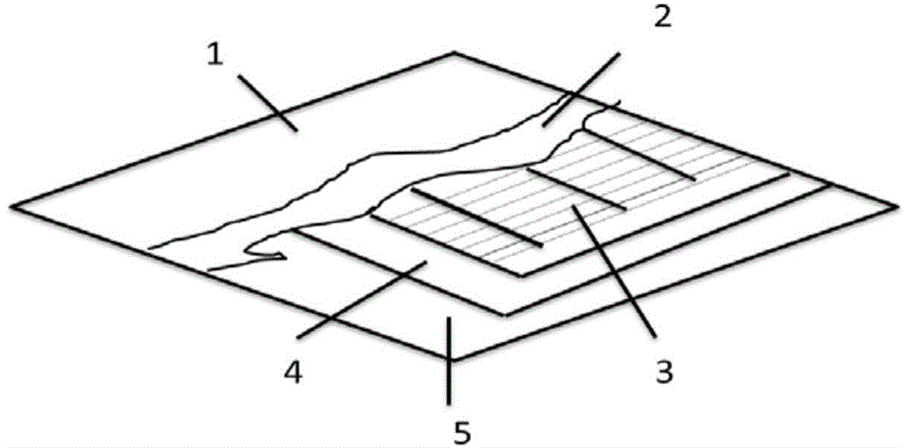
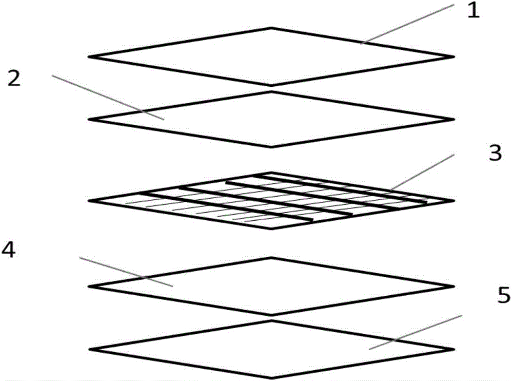
The invention provides a flexible film solar cell packaging method and a solar cell. The solar cell comprises a backboard (5), a solar cell sheet (3) and a transparent water-vapor-resistant high-molecular film (1). One side of the solar cell sheet (3) is laminated on the backboard (5) through a first hot melt adhesive (4), and the other side of the solar cell sheet (3) is laminated on the transparent water-vapor-resistant high-molecular film (1) through a second hot melt adhesive (2). Plastic hot melt adhesives package the solar cell therein and form a complex under a certain temperature and pressure so as to protect the solar cell; a packaged solar cell is flexible, and is not easy to break and damage in installation and use processes, thereby widening the application field of a film solar module.

Description

technical field [0001] The invention belongs to the technical field of solar cell encapsulation, and in particular relates to a method for encapsulating a flexible thin-film solar cell and the solar cell. Background technique [0002] Solar cells are the core components of solar power generation systems, and also the most valuable components in solar power generation systems. [0003] In the prior art, glass-encapsulated solar cells are generally used. This type of encapsulation mainly has the following problems: (1) The thickness of the solar cell obtained after encapsulation is relatively large. On the one hand, it is inconvenient to carry and install; on the other hand, it is difficult to apply (2) The solar cells obtained after encapsulation are relatively rigid, and are easily broken and damaged during installation and use. Contents of the invention [0004] Aiming at the defects in the prior art, the present invention provides a packaging method for flexible thin-fi...

Claims


Application Information

Patent Timeline
Patent Type & Authority Applications(China)
IPC IPC(8): H01L31/18H01L31/048B32B37/02
CPCY02E10/50Y02P70/50
Inventor 任宇航李龙吴文涛左凯峰
Owner 浙江尚越新能源开发有限公司
Learn More