
Transflective dual-edge doppler wind lidar based on single-cavity F-P interferometer and single detector

A wind-measuring lidar and single-detector technology, which is applied in the direction of instruments, measuring devices, and electromagnetic wave re-radiation, can solve the problems of waste of reflected signals, increase system correction parameters, and different coupling efficiencies, and achieve high wind speed detection accuracy. The effect of high signal utilization and compact structure

Active Publication Date: 2015-11-25
国耀量子雷达科技有限公司
View PDF7 Cites 25 Cited by
  • Summary
  • Abstract
  • Description
  • Claims
  • Application Information

AI Technical Summary

Problems solved by technology

[0006] 1) The cost of the F-P interferometer and the detector is high, resulting in high system cost; 2) The utilization rate of the laser radar signal is not high, and multi-channel detection is realized by a spectroscopic device, while the reflected signal of the F-P interferometer is wasted; 3) Two The system of F-P interferometer and two detectors cannot avoid the system error caused by the inconsistency of the working environment. For example, different ambient temperatures will lead to different noise distributions of the detectors; different input voltages of the detectors will lead to different responses of the detectors; When the radar is in a vibrating environment, the coupling efficiencies of the two detectors are different; in addition, optical pollution and detector aging problems will inevitably cause differences in the detectors; 4) dual channels make it difficult to adjust the optical path, and increase the system correction parameters

Method used


Image

  • Transflective dual-edge doppler wind lidar based on single-cavity F-P interferometer and single detector
  • Transflective dual-edge doppler wind lidar based on single-cavity F-P interferometer and single detector
  • Transflective dual-edge doppler wind lidar based on single-cavity F-P interferometer and single detector

Examples


Embodiment

[0028] figure 1 A schematic structural diagram of a transflective dual-edge wind-measuring lidar realized by a single-cavity F-P interferometer and a single detector provided by an embodiment of the present invention. Such as figure 1 As shown, it mainly includes: continuous laser 1, optical fiber isolator 2, intensity modulator 3, arbitrary function generator 4, optical fiber amplifier 5, first optical fiber circulator 6, calibration optical fiber 7, optical transceiver and scanning system 8, optical fiber Bragg grating 9, second optical fiber circulator 10, optical fiber F-P interferometer 11, time-delay optical fiber 12, optical fiber coupler 13, detector 14, acquisition card 15 and computer 16; wherein the connection relationship of each device is:

[0029] The output end of the continuous laser 1 is connected to the input end of the fiber isolator 2, the output end of the fiber isolator 2 is connected to the input end of the intensity modulator 3, the output end of the i...


PUM


Abstract

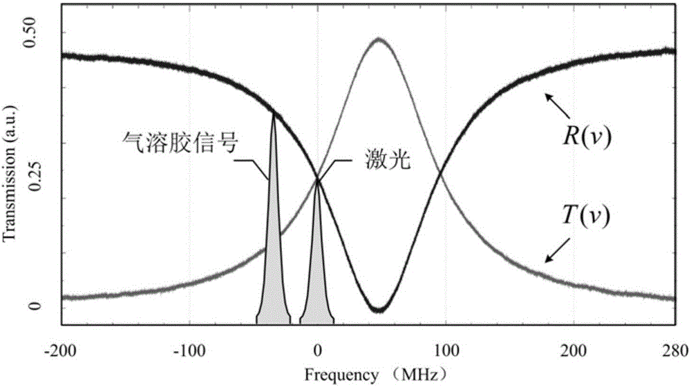
The invention discloses a transflective dual-edge doppler wind lidar based on a single-cavity F-P interferometer and a single detector. The doppler wind lidar comprises a single-cavity F-P interferometer as a frequency detector, wherein the transmission curve and the reflection curve of the single-cavity F-P interferometer form two edges. The intersection point of the transmission curve and the reflection curve of the single-cavity F-P interferometer locks the laser output frequency, so that the dual-edge wind speed detection technique is realized. The transflective dual-edge doppler wind lidar is designed based on the time division multiplexing technique. Since a low-loss fiber delay line is additionally arranged in the reflection light path of the single-cavity F-P interferometer, the transflective signals of the single-cavity F-P interferometer can be acquired at the same time by a single detector. The dual-edge detection technique is realized based on the single-cavity F-P interferometer and the single detector, and the transflective dual-edge doppler wind lidar has the advantages of high utilization rate of laser radar signals, high precision of wind speed detection, low cost, stable system, relative safety for human eyes, all-fiber-optic link, compact structure and the like.

Description

technical field [0001] The invention relates to the technical field of Doppler wind-measuring lidar, in particular to a transflective double-edge wind-measuring lidar realized by a single-cavity F-P interferometer and a single detector. Background technique [0002] Wind lidar is of great significance to improve the accuracy of long-term weather forecasts, improve climate research models, and improve military environment forecasts. Therefore, the measurement of atmospheric wind field has received more and more attention. Organizations such as the International Civil Aviation Agency, the World Meteorological Organization, and aerospace research institutions in various countries are actively carrying out research and development of wind field detection systems. [0003] Doppler wind lidar can be divided into coherent detection and direct detection according to different detection principles. Coherent detection detects wind speed detection by means of coherent laser atmospheri...

Claims


Application Information

Patent Timeline
IPC IPC(8): G01S17/95G01S7/481
CPCG01S7/4818G01S17/95Y02A90/10
Inventor 夏海云上官明佳窦贤康王冲薛向辉
Owner 国耀量子雷达科技有限公司
Learn More