
Mechanical displacement coupling and decoupling mechanism

A displacement and mechanical technology, applied in mechanical equipment, belts/chains/gears, transmissions, etc., can solve problems such as mutual interference and disputes, and achieve the effects of mechanical displacement decoupling, clear working process and simple principle.

Active Publication Date: 2017-05-17
XIAN AIRCRAFT DESIGN INST OF AVIATION IND OF CHINA
View PDF5 Cites 0 Cited by
  • Summary
  • Abstract
  • Description
  • Claims
  • Application Information

AI Technical Summary

Problems solved by technology

[0004] For the mechanical displacement coupling and decoupling of the dual-input and dual-output type, there are many problems: 1. The mutual interference between the two inputs. For the multi-input and single-output mechanism, generally between multiple input points There will be forces, mutual constraints, and disputes will appear; 2. The linear superposition problem between the outputs. Between the two output terminals, it is necessary to strictly control the output displacements corresponding to each input signal to be linearly superimposed and not affect each other. of

Method used


Image

  • Mechanical displacement coupling and decoupling mechanism

Examples


Embodiment Construction

[0018] The present disclosure will be described in further detail below in conjunction with the accompanying drawings.

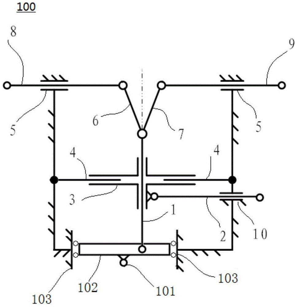
[0019] figure 1 is a schematic diagram illustrating the structure of the mechanical displacement coupling and decoupling mechanism 100 according to the present disclosure. Such as figure 1 As shown, the mechanical displacement coupling and decoupling mechanism 100 includes an input slideway 102, an input rod A 1, an input rod B 2, a cross sleeve 3, an intermediate connecting rod A 6, an intermediate connecting rod B 7, an output rod A 8, an output Rod B 9, core rail 4, input pipe rail 10, output pipe rail 5, side rail 103. The input slideway 102 is a groove-shaped slideway with an input point 101 fixed on the side, two sets of side rails 103 are arranged on both sides, and the input slideway 102 can move linearly along the side rails 103 . The input rod armor 1 is installed in parallel with two sets of side rails 103, the rod body passes through a sleeve ...


PUM


Abstract

The invention provides a mechanical displacement coupling and decoupling mechanism. In the mechanism, an input slideway is in a groove shape, an input point is fixed to the side edge of the input slideway, two sets of side rails are arranged on the two sides of the input slideway, and the input slideway can linearly move along the side rails. A first input rod is parallel to the two sets of side rails, a rod body penetrates in a casing pipe of a cross-shaped sleeve, one end of the first input rod is arranged in cooperation with the input slideway and can slide along the input slideway, and the other end of the first input rod is hinged to a first middle connecting rod and a second middle connecting rod. The other end of the first middle connecting rod is hinged to a first output rod, and the other end of the second middle connecting rod is hinged to a second output rod. The other two ends of the cross-shaped sleeve are arranged on core rails in a sleeving manner respectively and can horizontally move along the core rails, the first output rod and the second output rod penetrate two output pipe rails respectively and can horizontally move along the output pipe rails, and a second input rod penetrates an input pipe rail and is fixedly connected with a cross-shaped pipe rail. The motion direction of the first input rod is always perpendicular to that of the second input rod, and the input pipe rail, the core rails, the output pipe rails and the side rails are all fixed rails. The mechanism is simple in principle, clear in work process, easy to implement and precise in design.

Description

technical field [0001] The present disclosure relates to mechanism design in the field of mechanical design, in particular to a mechanical displacement coupling and decoupling mechanism. Background technique [0002] In the current field of mechanical design, the traditional mechanism is considered to be the easiest to use and also the most reliable and safe mechanism. Especially for the mechanism of connecting rods, the elements of the connecting parts of each unit have incomparable advantages in terms of manufacturing accuracy and manufacturing cost. The link mechanism is generally used in mechanical transmission, especially in planar or spatial bar system motion mechanisms, and is widely used as mechanical displacement transmission. It is generally a single-input or single-output type, that is to say, one input point corresponds to multiple output points, or multiple input points correspond to one output point. [0003] However, it is difficult to implement the link mec...

Claims


Application Information

Patent Timeline
Patent Type & Authority Patents(China)
IPC IPC(8): F16H21/10
CPCF16H21/10
Inventor 王慧闫东
Owner XIAN AIRCRAFT DESIGN INST OF AVIATION IND OF CHINA
Learn More