
Oil injection system facilitating adjustment of oil injection state

A fuel injection system and state technology, applied in the system field, can solve problems such as poor fuel injection efficiency, clogging of fuel injectors, complex structure, etc., and achieve the effects of reducing the probability of clogging, prolonging the service life, and improving fuel injection efficiency

Inactive Publication Date: 2015-11-25
四川膨旭科技有限公司
View PDF6 Cites 2 Cited by
  • Summary
  • Abstract
  • Description
  • Claims
  • Application Information

AI Technical Summary

Problems solved by technology

[0003] The purpose of the present invention is to overcome the complex structure of the fuel injection device of the existing automobiles, which often causes the fuel injection nozzle to be blocked, resulting in poor fuel injection efficiency and high maintenance costs, and the user cannot understand the internal state of the fuel injector and cannot timely To deal with some potential minor problems, a fuel injection system that is easy to adjust the fuel injection state is designed. By improving the structure, the system enables users to understand the internal operating conditions of the fuel injector, and can deal with some potential problems in time. Small problems can be prevented from expanding, and the probability of clogging in the fuel injection process can be reduced, the fuel injection efficiency can be improved, and the service life can be extended. The oil efficiency is poor, the maintenance cost is high, and the user cannot understand the internal state of the injector, and cannot deal with some potential minor problems in time

Method used


Image

  • Oil injection system facilitating adjustment of oil injection state

Examples


Embodiment

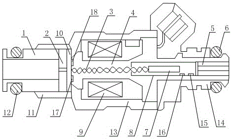
[0012] Such as figure 1 As shown, the fuel injection system that is convenient to adjust the fuel injection state includes a fuel injector body 13 that is hollow inside and has openings at both ends. The fuel injector body 13 is provided with an iron core 4, and the centerline of the iron core 4 and the injector The center line of the injector body 13 coincides, the outer wall of the iron core 4 is covered with an electromagnetic coil 9, and the electromagnetic coil 9 is arranged in the sealed space formed by the injector body 13 and the iron core 4, and the injector body 13 is connected to a limited position. Cover 11, the opening end of the limit sleeve 11 communicates with the open end of the injector body 13, the nozzle cover 1 is arranged in the limit cover 11, the nozzle cover 1 can move horizontally in the limit cover 11, the nozzle cover 1 A sealing ring 12 is sleeved on the outer wall, and the sealing ring 12 can be seamlessly fitted when in contact with the inner wal...


PUM


Abstract

The invention discloses an oil injection system facilitating adjustment of the oil injection state. An iron core is arranged in an oil injector and sleeved with an electromagnetic coil. The oil injector is connected with a limiting sleeve. A nozzle sleeve is arranged in the limiting sleeve. The outer wall of the nozzle sleeve is sleeved with a first sealing ring. A valve seat is arranged in the limiting sleeve. The valve seat is connected with a valve plate. A second pressure sensor and a second temperature sensor are arranged in the oil injector. The oil injector is provided with an installation sleeve. A protecting sleeve is arranged in the installation sleeve. A pressure-adjusting sliding block is arranged in the protecting sleeve. The pressure-adjusting sliding block is connected with a spring. The spring penetrates an opening of the protecting sleeve to be connected with the valve plate. A first pressure sensor and a first temperature sensor are arranged in the protecting sleeve. By means of the system, internal operating conditions of the oil injector can be known, and some small potential problems can be solved in time and prevented from getting worse; and the probability of blockage occurring in the oil injection process is reduced, the oil injection efficiency is improved, and the use cycle is prolonged.

Description

technical field [0001] The invention relates to a system, in particular to a fuel injection system which is convenient for adjusting the fuel injection state. Background technique [0002] Automobile is a vehicle that can be driven by its own power, and can be driven by motor without the need for rails or electric power. In a broad sense, a vehicle with four wheels is generally called a car. From the end of the 19th century to the beginning of the 20th century, automobile designers devoted their energy to the development and innovation of automobile mechanical engineering. In the first half of the 20th century, after the basic structure of the car had been invented, car designers began to improve the exterior shape of the car, and successively introduced aerodynamics, fluid mechanics, ergonomics and industrial design (industrial design). Aesthetics) and other concepts, and strive to make the car meet the different needs of people of various ages, classes, and even cultural...

Claims


Application Information

Patent Timeline
Patent Type & Authority Applications(China)
IPC IPC(8): F02M51/06F02M63/00
Inventor 代膨岭
Owner 四川膨旭科技有限公司
Learn More