
Vertical cold isostatic press

A cold isostatic press, vertical technology, used in presses, mechanical equipment, engine components, etc., can solve problems such as heavy overall mass and large torque

Active Publication Date: 2015-11-25
陈烈
View PDF5 Cites 0 Cited by
  • Summary
  • Abstract
  • Description
  • Claims
  • Application Information

AI Technical Summary

Problems solved by technology

The sealing end cover includes a separate sealing seat and a threaded fixing seat, and the two can rotate independently relative to each other. The side wall of the sealing seat is provided with a sealing ring structure that cooperates with the high-pressure vessel. When the high-pressure vessel is sealed and matched, the sealing seat and the threaded fixing seat are set separately. When the threaded fixing seat and the high-pressure vessel are rotated and threaded, the sealing seat can be axially fed into the high-pressure vessel separately, and the seal on it The ring will not produce corresponding rotational friction with the high-pressure vessel, and finally the threaded fixing seat is against the sealing seat in the sealed state, but such a structure is currently only used for horizontal structures
[0003] The present invention aims to apply this solution to the cold isostatic press of vertical structure based on the above-mentioned matching structure of the sealing seat and the threaded fixing seat, but there are the following problems in the process of technology transfer: due to the overall The quality is relatively heavy, generally hundreds of kilograms or even heavier. At the same time, during the sealing process of the sealing end cover, the threaded fixing seat generates a large friction force with the sealing seat during the rotation process. For the threaded fixing seat Thread fit with high pressure vessels requires high torque

Method used


Image

  • Vertical cold isostatic press
  • Vertical cold isostatic press

Examples


Embodiment Construction

[0018] The specific implementation manners of the present invention will be further described in detail below in conjunction with the accompanying drawings and embodiments. The following examples are used to illustrate the present invention, but are not intended to limit the scope of the present invention.

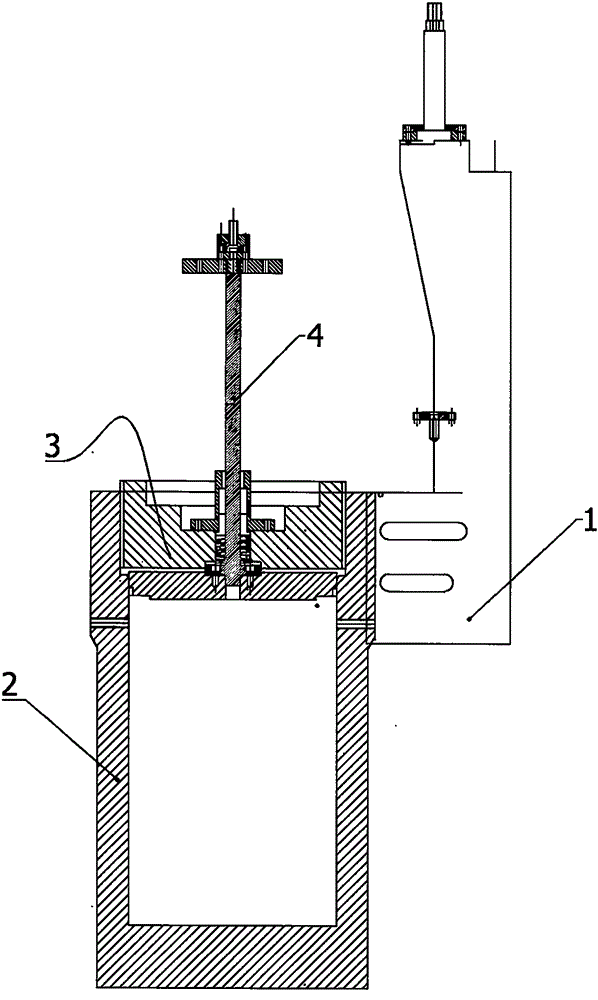
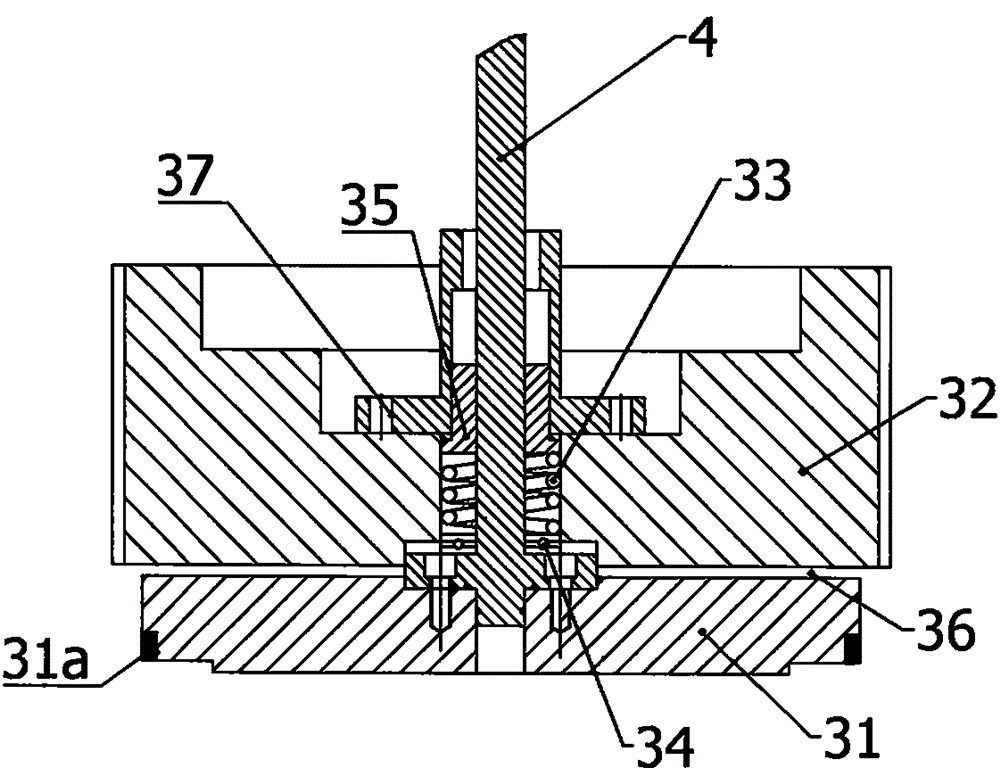
[0019] Such as Figure 1 to Figure 2 As shown, the vertical cold isostatic press includes a frame structure 1, a vertically arranged high-pressure vessel 2 with an open top, and a sealing end cap 3 that is threadedly fitted to the opening end of the high-pressure vessel 2, and the sealing end The cover 3 includes a threaded fixing seat 32 and a sealing seat 31 which are separately arranged up and down. The threaded fixing seat 32 is threaded and fixedly matched with the high-pressure vessel 2. The sealing seat 31 is provided with a sealing ring 31a and is sealed and matched with the high-pressure vessel 2. The threaded fixing seat 32 It can be independently rotated relati...


PUM


Abstract

The invention provides a vertical cold isostatic press. The vertical cold isostatic press is characterized by comprising a high-pressure container and a seal end cover, wherein the high-pressure container is vertically arranged, and the top of the high-pressure container is open; the seal end cover is fixedly matched with the open end of the high-pressure container in a threaded manner, and the seal end cover comprises a threaded fixing seat and a seal seat which are arranged in a vertically split manner; the threaded fixing seat is fixedly matched with the high-pressure container in a threaded manner, and the seal seat is matched with the high-pressure container in a sealed manner; the threaded fixing seat can rotate independently relative to the seal seat, and an elastic mechanism is arranged between the threaded fixing seat and the seal seat; the elastic mechanism enables a certain separation gap to be formed between the threaded fixing seat and the seal seat, and the seal seat is connected to a connecting shaft penetrating through the center of the threaded fixing seat; and the connecting shaft is connected to a suspension mechanism enabling the seal end cover to be in a balance force state. By the adoption of the vertical cold isostatic press, on the basis of a horizontal type cold isostatic press, the situation that wear of a seal ring on the seal end cover is accelerated due to rotation is avoided, and meanwhile the vertical cold isostatic press is high in working stability, low in operation load, capable of being rapidly started and convenient to use.

Description

technical field [0001] The invention relates to a cold isostatic press, in particular to a vertical cold isostatic press. Background technique [0002] The structure of the existing cold isostatic press is generally composed of a high-pressure container and a sealed end cover. The end cover cooperates with the high-pressure container to achieve sealing, and a certain pressure is applied to the elastic mold with liquid or gas to press the material into a solid body to obtain the original shape of the green body. After the pressure is released, the elastic mold is taken out from the high-pressure container and demoulded. . The sealing end cover includes a separate sealing seat and a threaded fixing seat, and the two can rotate independently relative to each other. The side wall of the sealing seat is provided with a sealing ring structure that cooperates with the high-pressure vessel. When the high-pressure vessel is sealed and matched, the sealing seat and the threaded fixi...

Claims


Application Information

Patent Timeline
IPC IPC(8): B30B12/00F16J15/16
Inventor 陈烈
Owner 陈烈
Learn More