
A two-dimensional vibration-assisted laser scanning in-position detection system and its detection method

An auxiliary laser and two-dimensional vibration technology, which is applied in the direction of measuring/indicating equipment, metal processing machinery parts, metal processing equipment, etc., can solve the problems of low detection efficiency, insufficient precision, high price, etc., achieve reliable detection accuracy and improve detection Accuracy, cost and error reduction effects

Active Publication Date: 2017-06-16
SHANGHAI JIAOTONG UNIV
View PDF7 Cites 0 Cited by
  • Summary
  • Abstract
  • Description
  • Claims
  • Application Information

AI Technical Summary

Problems solved by technology

[0004] In order to solve the problems of in-position detection and at the same time overcome the problems of low detection efficiency, insufficient precision and high price, the object of the present invention is to provide a two-dimensional vibration-assisted laser scanning in-position detection system, including follow-up guide rails and X-axis guide rails, and The follow-up guide rail is matched with the follow-up guide rail connector; the follow-up guide rail is parallel to the X-axis guide rail and can slide back and forth along the X-axis guide rail direction, while the follow-up guide rail connector is in the X-axis direction stay still

Method used


Image

  • A two-dimensional vibration-assisted laser scanning in-position detection system and its detection method
  • A two-dimensional vibration-assisted laser scanning in-position detection system and its detection method
  • A two-dimensional vibration-assisted laser scanning in-position detection system and its detection method

Examples


Embodiment Construction

[0034] The present invention will be further described below in conjunction with the accompanying drawings.

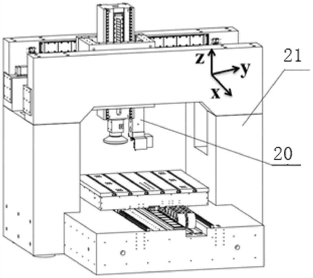
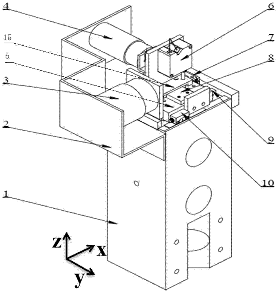
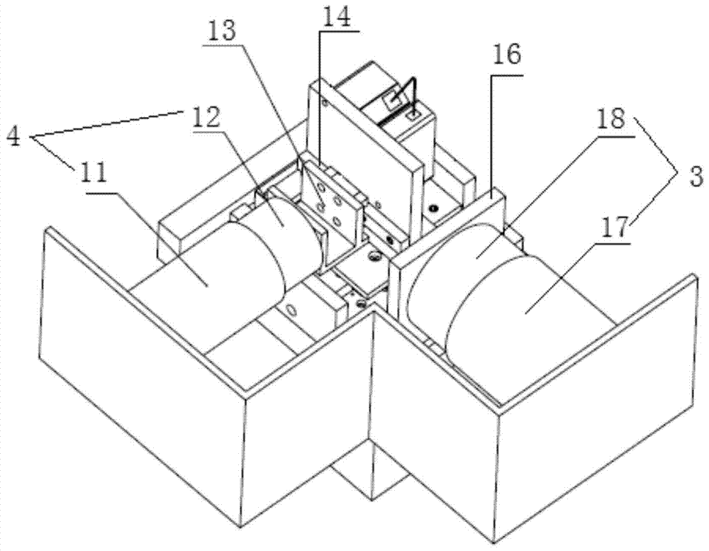
[0035] Such as figure 1 Shown is an integration diagram of a specific implementation of the two-dimensional vibration-assisted laser scanning in-position detection system of the present invention and an ultra-precision grinding machine. Its detection object can be a large space mirror. The two-dimensional vibration-assisted laser scanning in-position detection system 20 is integrated on the main shaft of the grinding machine 21 and can move together with the main shaft. A grinder is a type of machine tool. The two-dimensional vibration-assisted laser scanning in-situ inspection system, such as figure 2 with 3As shown, it includes vibration platform base 1, motor fixed support 2, Y-axis voice coil motor 4, follow-up guide rail connector 13, follow-up guide rail 14, laser displacement sensor 6, Y-axis motion platform 15, Y-axis guide rail 8 , Y-axis grating 7, X-ax...


PUM


Abstract

The invention discloses a two-dimensional vibration auxiliary laser scanning in-situ detection system which comprises a servo guide rail, an X-axis guide rail and a servo guide rail connecting piece connected with the servo guide rail in a matched manner and further comprises a Y-axis voice coil motor, a laser displacement sensor, an X-axis voice coil motor and an X-axis movement platform. The servo guide rail is parallel to the X-axis guide rail and can slide back and forth along the X-axis guide rail and the servo guide rail connecting piece remains still in the X-axis direction. Due to the arrangement of the servo guide rail, the Y-axis voice coil motor connected with the servo guide rail connecting piece can remain still when the servo guide rail is pulled by the laser displacement sensor to move along the X-axis guide rail, the mass of the Y-axis voice coil motor cannot become the resistance of movement of the laser displacement sensor in the X-axis direction, and the power and the size of the X-axis voice coil motor do not need to be increased. By the adoption of the system, in-situ detection is achieved, the detection efficiency is good while accuracy is guaranteed, the anti-interference performance is good, and the system can be used on different occasions for detection of different targets.

Description

technical field [0001] The invention relates to an in-position detection system and a detection method thereof, in particular to a two-dimensional vibration-assisted laser scanning in-position detection system and a detection method thereof, belonging to the technical field of large-diameter optical mirror geometry measurement. Background technique [0002] With the rapid development of modern military and aerospace and the continuous breakthrough of advanced manufacturing technology, more and more large optical mirrors have been applied, and the precision requirements are getting higher and higher. However, when machining large-diameter optical mirrors on machine tools, in order to improve the machining accuracy, it is necessary to continuously process-test-process. At present, large-diameter optical mirrors are mainly detected by offline equipment. However, due to the large volume and weight of the mirror, it is not easy to move and is expensive. In order to ensure the saf...

Claims


Application Information

Patent Timeline
Patent Type & Authority Patents(China)
IPC IPC(8): B23Q17/24
CPCB23Q17/2471
Inventor 任明俊孙立剑殷跃红
Owner SHANGHAI JIAOTONG UNIV
Learn More