
In-situ detection device and detection method of free-form surface optical element

A technology of optical components and detection devices, which is applied in the field of ultra-precision detection of complex curved surfaces, can solve problems such as indistinguishable, overlapping error forms and processing errors, dynamic tracking errors, etc., and achieve the effect of compact structure, strong versatility, and small volume

Active Publication Date: 2019-06-14
NAT UNIV OF DEFENSE TECH
View PDF5 Cites 0 Cited by
  • Summary
  • Abstract
  • Description
  • Claims
  • Application Information

AI Technical Summary

Problems solved by technology

The former cannot realize the measurement and evaluation of free-form surfaces, while the latter has dynamic tracking errors, and the probe needs to be strictly aligned with the center of rotation of the spindle, otherwise the resulting errors are difficult to control, and the error form overlaps with the machining error, making it difficult to distinguish

Method used


Image

  • In-situ detection device and detection method of free-form surface optical element
  • In-situ detection device and detection method of free-form surface optical element
  • In-situ detection device and detection method of free-form surface optical element

Examples


Embodiment Construction

[0036] The present invention will be further elaborated below in conjunction with the accompanying drawings and specific embodiments.

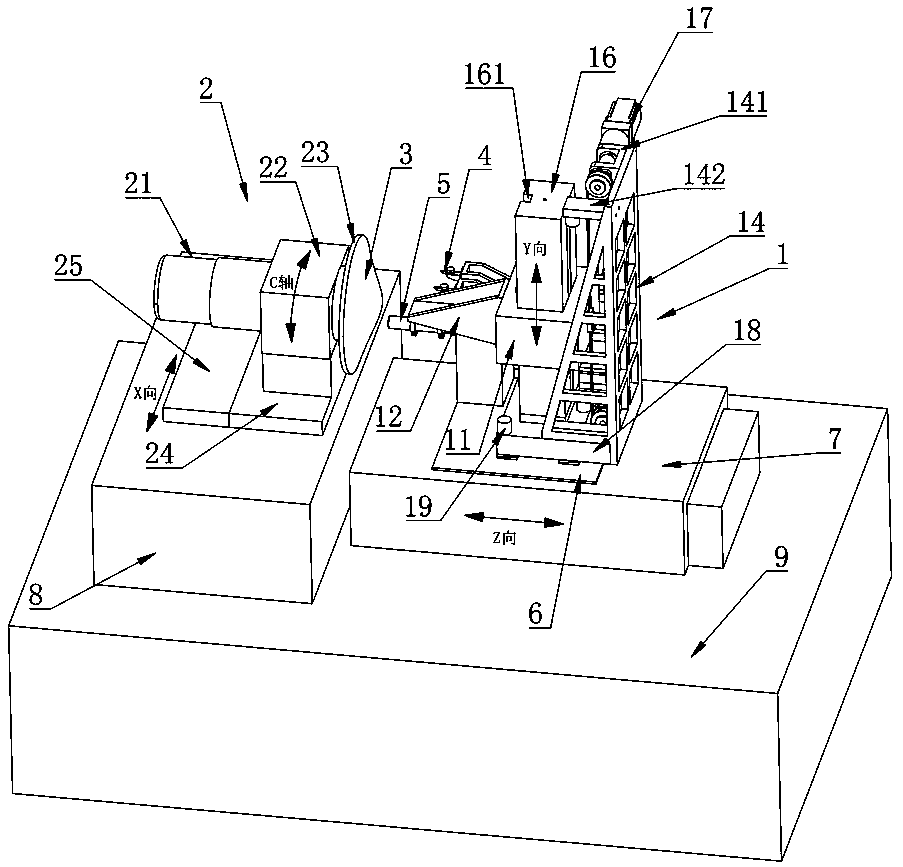
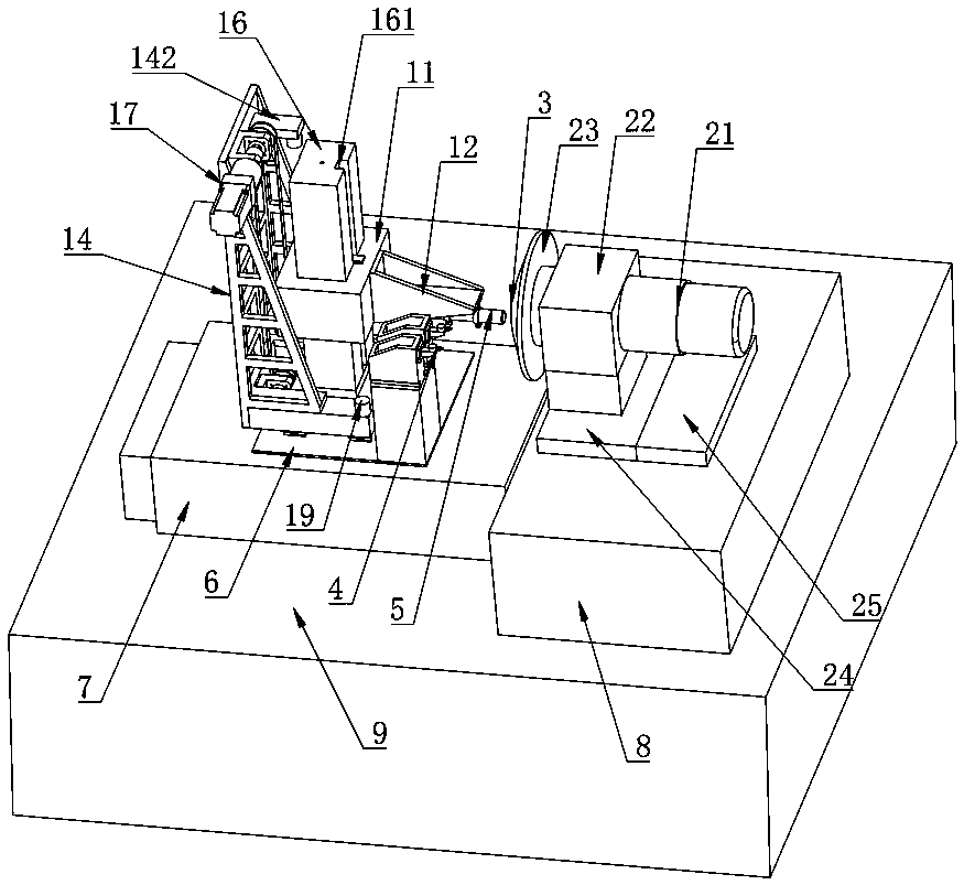
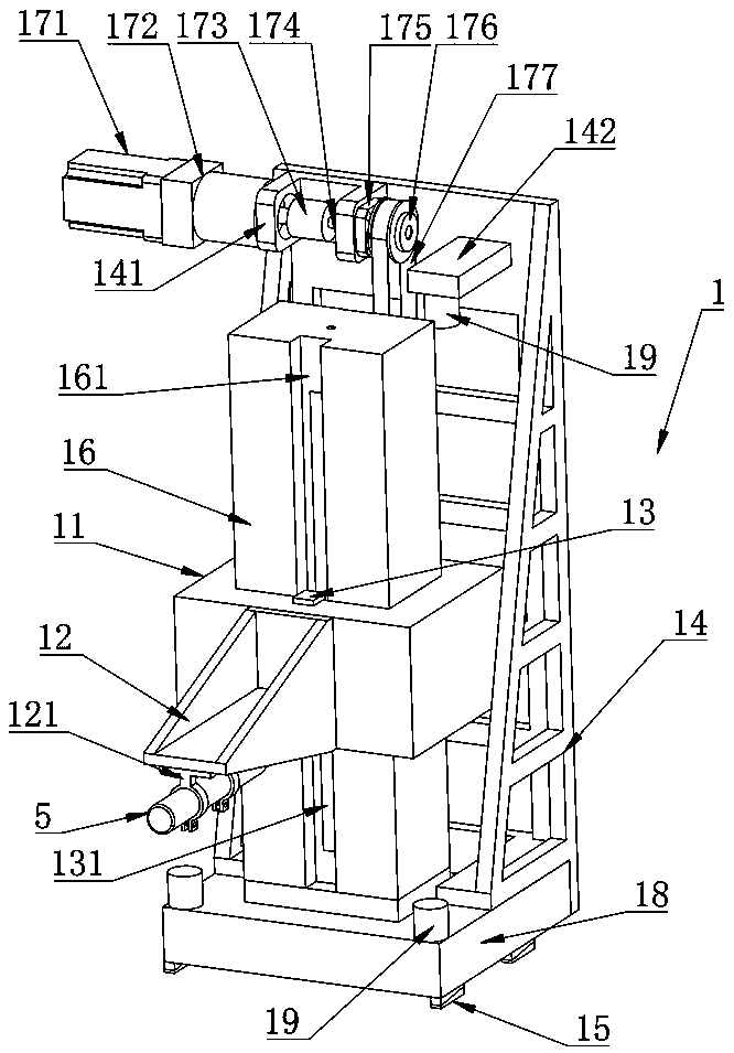
[0037] Such as Figures 1 to 8 As shown, an in-position detection device for a free-form surface optical element of the present invention includes a rotating main shaft 2, a Z axis 7, an X axis 8, and a Y-axis module 1 vertically arranged above the Z axis 7, and the rotating main shaft 2 is arranged horizontally Above the X-axis 8 and parallel to the Z-axis 7, the free-form surface optical element 3 is clamped on the rotating spindle 2. The Y-axis module 1 includes a slider 11 and a column 16. The slider 11 is slid on the column 16. The slider 11 is provided with a displacement sensor 5 for in-situ measurement of the free-form surface optical element 3 . The Y-axis module 1 vertically arranged above the Z-axis 7 forms three linear axes with the X-axis 8 and Z-axis 7 to realize spatial movement. The Y-axis module 1 includes a slider 11, a colu...


PUM


Abstract

The present invention discloses a free-form surface optical element on-line measurement device. The device comprises a rotation main shaft, a Z shaft, an X shaft and a Y shaft module vertically arranged at the upper portion of the Z shaft, the rotation main shaft is arranged at the upper portion of the X shaft and is parallel to the Z shaft, the rotation main shaft clamps a free-form surface optical element, the Y shaft module comprises a sliding block and a stand column, the sliding block is slidingly arranged on the stand column, and the sliding block is provided with a displacement sensor for on-line measurement of the free-form surface optical element. The present invention further provides a free-form surface optical element on-line measurement method. The device can realize the high-precision on-line measurement of the free-form surface optical element.

Description

technical field [0001] The invention relates to the field of ultra-precise detection of complex curved surfaces, in particular to an in-situ detection device and detection method for free-form surface optical elements. Background technique [0002] The free-form surface optical element is conducive to simplifying the system structure, reducing the number and size of the lens, improving the imaging quality, and obtaining many special optical properties, which brings great potential to the design of new products. Therefore, free-form surface optical components have more and more urgent demands in both military and civilian fields, such as large-scale astronomical observation systems, military photothermal imaging devices, missile guidance systems, digital display systems, automotive lighting systems, ophthalmic medical systems, etc. . At present, there are two main methods for in-situ detection of free-form surface optical components based on ultra-precision lathes: 1. Measur...

Claims


Application Information

Patent Timeline
Patent Type & Authority Patents(China)
IPC IPC(8): G01B11/24
CPCG01B11/24
Inventor 铁贵鹏彭小强戴一帆关朝亮陈善勇王贵林
Owner NAT UNIV OF DEFENSE TECH
Learn More