Battery presence detection circuit, method and smart wearable device

A detection circuit and discharge circuit technology, applied in the direction of measuring electricity, measuring devices, measuring electrical variables, etc., can solve problems such as high cost, smart wearable devices not working normally, and inability to confirm whether the battery is in place, etc.

Active Publication Date: 2021-07-13
GEER TECH CO LTD
View PDF4 Cites 0 Cited by
  • Summary
  • Abstract
  • Description
  • Claims
  • Application Information

AI Technical Summary

Problems solved by technology

[0002] At present, in the production process of smart wearable devices, most of them need to assemble batteries to drive the smart wearable devices to work. Once the installation is missing, the smart wearable devices may not work properly
[0003] In a small number of charging chips for batteries, there is an in-position detection module. However, the cost of such charging chips is relatively high, and most of them do not feed back the detection results to the main controller of the smart wearable device. The main controller cannot confirm whether the battery is reign

Method used


Image

  • Battery presence detection circuit, method and smart wearable device
  • Battery presence detection circuit, method and smart wearable device
  • Battery presence detection circuit, method and smart wearable device

Examples


Embodiment Construction

[0036] The following will clearly and completely describe the technical solutions in the embodiments of the present invention with reference to the accompanying drawings in the embodiments of the present invention. Obviously, the described embodiments are only some of the embodiments of the present invention, not all of them. Based on the embodiments of the present invention, all other embodiments obtained by persons of ordinary skill in the art without creative efforts fall within the protection scope of the present invention.

[0037] It should be noted that if there is a directional indication (such as up, down, left, right, front, back...) in the embodiment of the present invention, the directional indication is only used to explain the position in a certain posture (as shown in the accompanying drawing). If the specific posture changes, the directional indication will also change accordingly.

[0038] In addition, if there are descriptions involving "first", "second" and ...


PUM


Abstract

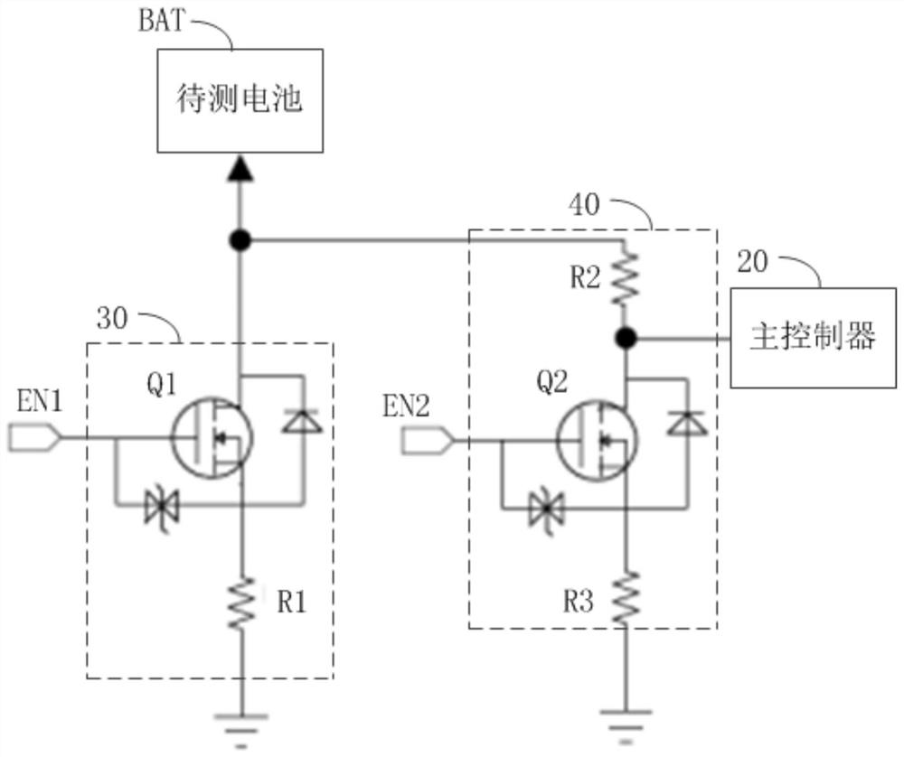
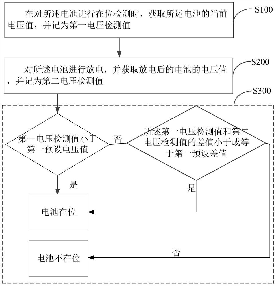
The invention discloses a battery in-position detection circuit, a method and an intelligent wearable device. The battery in-position detection circuit includes: a discharge circuit configured to discharge a battery to be tested when receiving a discharge control signal; a voltage division detection circuit configured to It is turned on when the detection control signal is received to detect the voltage of the battery under test; the main controller is set to determine that the battery under test is in place when the first voltage detection value before the battery under test is discharged is less than the first preset voltage value ; or under the condition that the first voltage detection value before the battery under test is discharged is greater than or equal to the first preset voltage value, the first voltage detection value before the battery under test is discharged and the second voltage detection value after the battery under test is discharged When the difference between the values ​​is less than or equal to the first preset difference, it is determined that the battery to be tested is in place. The invention realizes the in-position detection of the battery to be tested.

Description

technical field [0001] The invention relates to the technical field of electronic circuits, in particular to a battery presence detection circuit, method and smart wearable device. Background technique [0002] At present, in the production process of smart wearable devices, most of them need to assemble batteries to drive the smart wearable devices to work. Once the installation is missing, the smart wearable devices may not work properly. [0003] In a small number of charging chips for batteries, there is an in-position detection module. However, the cost of such charging chips is relatively high, and most of them do not feed back the detection results to the main controller of the smart wearable device. The main controller cannot confirm whether the battery is reign. Contents of the invention [0004] The main purpose of the present invention is to propose a battery presence detection circuit, method and smart wearable device, aiming at realizing battery presence dete...

Claims


Application Information

Patent Timeline
Patent Type & Authority Patents(China)
IPC IPC(8): G01R31/385
Inventor 刘辉
Owner GEER TECH CO LTD
Why Eureka
Try Eureka