Eureka AIR delivers breakthrough ideas for toughest innovation challenges, trusted by R&D personnel around the world.

Functional magnetic resonance imaging synchronous monitoring and triggering stimulation control system

A technology of functional magnetic resonance and magnetic resonance imaging, applied in diagnostic recording/measurement, medical science, diagnosis, etc., can solve problems such as doubts about the scientific nature of experimental results, equipment that cannot be synchronized in time, and data reliability reduction

Active Publication Date: 2015-11-25
CENT FOR EXCELLENCE IN BRAIN SCI & INTELLIGENCE TECH CHINESE ACAD OF SCI
View PDF3 Cites 12 Cited by
  • Summary
  • Abstract
  • Description
  • Claims
  • Application Information

AI Technical Summary

Problems solved by technology

[0004] However, at present, the research on the implementation methods, types and structures of simultaneous physiological monitoring and trigger stimulation in primate (including human) fMRI experiments is not perfect. The design of the experimental program for the purpose of the experiment greatly reduces the repeatability of the experiment and makes the scientific nature of the experimental results questioned.
Not only that, because it involves the cooperation of multiple devices, experimenters often need to operate multiple devices at the same time, and the devices cannot be synchronized in time, which further reduces the reliability of the data

Method used


Image

  • Functional magnetic resonance imaging synchronous monitoring and triggering stimulation control system
  • Functional magnetic resonance imaging synchronous monitoring and triggering stimulation control system
  • Functional magnetic resonance imaging synchronous monitoring and triggering stimulation control system

Examples


Embodiment Construction

[0049] The above-mentioned features and advantages of the present invention can be better understood after reading the detailed description of the embodiments of the present disclosure in conjunction with the following drawings. In the drawings, components are not necessarily drawn to scale, and components with similar related properties or characteristics may have the same or similar reference numerals.

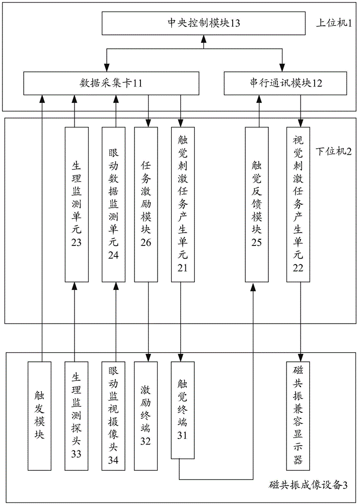
[0050] figure 1 The principle of a preferred embodiment of the fMRI synchronous monitoring and triggering stimulation control system of the present invention is shown. Please also see figure 1 , the system of this embodiment includes: a host computer 1 , a slave computer 2 and a magnetic resonance imaging device 3 .

[0051]In this embodiment, the upper computer 1 is used for man-machine interaction and control of the lower computer 2 . For the operation of human-computer interaction, for example, it is realized through the LabView human-machine interface software program...


PUM


Abstract

The invention discloses a functional magnetic resonance imaging synchronous monitoring and triggering stimulation control system. The technical scheme includes that the system comprises an upper computer, a lower computer and magnetic resonance imaging equipment; the upper computer is used for carrying out man-machine interaction and controlling the lower computer; the lower computer is used for processing communication and interaction with the magnetic resonance imaging equipment, stimulation tasks can be generated by a stimulation task generating module in the lower computer on the basis of instructions emitted by the upper computer, a monitoring module in the lower computer is communicated with the upper computer, and reaction parameters, which are measured by the magnetic resonance imaging equipment, of tested objects can be recorded when the stimulation tasks are carried out, and can be fed to the upper computer. The functional magnetic resonance imaging synchronous monitoring and triggering stimulation control system has the advantages that central control and hardware interfaces can be unified, triggering signals can be synchronously received when magnetic resonance images are scanned, various physiological parameters of primates can be synchronously recorded, and the functional magnetic resonance imaging synchronous monitoring and triggering stimulation control system is suitable for software and hardware technical platforms for the stimulation tasks for vision, touch and the like of the primates.

Description

technical field [0001] The invention relates to a magnetic resonance imaging matching device, in particular to a functional magnetic resonance imaging synchronous monitoring and trigger stimulation control system. Background technique [0002] In recent years, functional magnetic resonance imaging (fMRI), as an emerging research method, has been widely used in the field of cognitive neuroscience research to explore the brain mechanism of human cognitive processes and emotional activities. In addition to directly using humans as research objects, non-human primates, as the closest relatives of humans, have brain structures similar to humans and possess advanced brain functions, and can be trained to complete specific types of test tasks. It has an irreplaceable role in evaluating cognitive ability and emotional response, etc., and is an ideal animal model for basic research on the normal function of the human brain and disease pathology research. A direct effect of these res...

Claims


Application Information

Patent Timeline
Patent Type & Authority Applications(China)
IPC IPC(8): A61B5/055
Inventor 彭金强俞文文王志伟吕骞王征
Owner CENT FOR EXCELLENCE IN BRAIN SCI & INTELLIGENCE TECH CHINESE ACAD OF SCI
Why Eureka
Eureka Blog
Learn More