Method for cleaning a combustion chamber of an internal combustion engine and internal combustion engine

A technology for internal combustion engines and combustion chambers, applied in combustion engines, internal combustion piston engines, combustion air/combustion-air treatment, etc., can solve problems such as complex injection devices, and achieve continuous cleaning effects

Inactive Publication Date: 2018-07-17
MOTOREN UND TURBINEN UNION MUNCHEN GMBH
View PDF6 Cites 0 Cited by
  • Summary
  • Abstract
  • Description
  • Claims
  • Application Information

AI Technical Summary

Problems solved by technology

The disadvantage of this approach is that complex injection devices are required for the introduction of water

Method used


Image

  • Method for cleaning a combustion chamber of an internal combustion engine and internal combustion engine

Examples


Embodiment Construction

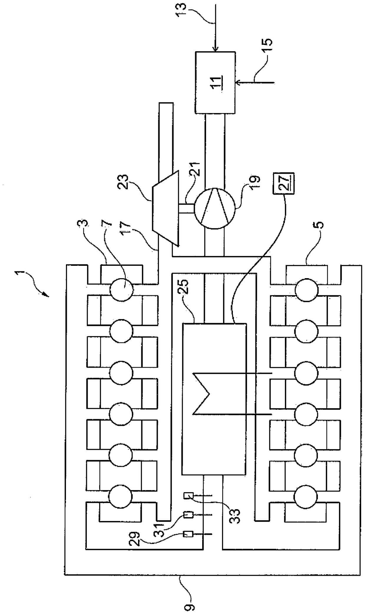
[0025] The drawing shows a schematic illustration of an exemplary embodiment of an internal combustion engine 1 . The internal combustion engine is here configured as a twelve-cylinder V-engine with a first cylinder bank 3 and a second cylinder bank 5, wherein each of the cylinder banks 3, 5 comprises six combustion chambers, where for better Only one of them is marked with reference number 7 for reasons of clarity. The gaseous substance is fed to the combustion chamber 7 via the feed line 9 . In the exemplary embodiment shown, this substance is formed as a mixture which is prepared in a gas mixer 11 from combustion air 13 and fuel 15 .

[0026] Combustion reactions are known to take place in the combustion chamber 7 , wherein residues, in particular exhaust gases, are produced, which are discharged via the discharge line 17 .

[0027] Downstream of the gas mixer 11 , the gas mixture is compressed in a compressor 19 , which is here driven via a shaft 21 by a turbine 23 , whi...


PUM


Abstract

The invention proposes a method for cleaning a combustion chamber (7) of an internal combustion engine (1), comprising the following steps: introducing a gaseous substance into a cooling device (25), wherein the gaseous substance is at least in the cooling device (25) ) upstream has a relative humidity greater than 0%; cools the substance below the dew point in the cooling device (25), thereby forming condensation of water; introduces the substance including the condensation into the combustion chamber (7) of the internal combustion engine (1) ; carrying out the combustion reaction in the combustion chamber (7); and leading out the residue from the combustion chamber (7).

Description

technical field [0001] The invention relates to a method according to the invention for cleaning a combustion chamber of an internal combustion engine and an internal combustion engine according to the invention. Background technique [0002] The problem typically exists in internal combustion engines that deposits (Ablagerung) form in the combustion chamber over time due to continuous combustion reactions in at least one combustion chamber, which include, for example, putty (Ölasche) and / or Combustion of dirt conveyed by air. Especially in the case of internal combustion engines designed as gas engines, such deposits can lead to knocking, which in turn leads to a reduction in the service life and maximum power of the internal combustion engine. It is therefore necessary to clean such internal combustion engines at predetermined intervals or also as required or to free the combustion chamber from deposits. For this purpose, it is typically provided that the internal combus...

Claims


Application Information

Patent Timeline
Patent Type & Authority Patents(China)
IPC IPC(8): F02B77/04F02B29/04
CPCF02B29/0468F02B29/0493F02B77/04F02D2200/0418F02M25/0222F02M25/03F02M35/1038F02M35/10393Y02T10/12
Inventor B.施蒂勒
Owner MOTOREN UND TURBINEN UNION MUNCHEN GMBH
Why Eureka
Try Eureka