Suction oil filter with bypass

An oil suction filter and bypass technology, applied in the direction of filtration and separation, machine/engine, engine lubrication, etc., can solve the problems of no filtering effect, dirty bypass filter, small filtering area, etc., to prevent and quickly get dirty. Dirty, continuous cleaning effect

Active Publication Date: 2011-12-14
ZF FRIEDRICHSHAFEN AG
View PDF4 Cites 0 Cited by
  • Summary
  • Abstract
  • Description
  • Claims
  • Application Information

AI Technical Summary

Problems solved by technology

However, it has been found that in normal operating conditions of the system in which the oil to be circulated is of low viscosity when using a correspondingly constructed suction filter, pressure fluctuations can occur on the suction side, caused by brief negative pressures , this negative pressure may accidentally cause the bypass to open
However, this is undesirable since a complete filtering effect is generally not provided in the area of ​​the bypass
Here, the risk of larger foreign particles passing through the open bypass valve increases
Furthermore, with the filter arrangement according to the aforementioned document, there is also the risk that the bypass filter arranged in the bypass can quickly become soiled and thus at least partially clogged, so that the bypass filter can no longer be completely ensured. road function
This danger arises because the relatively small filter area of ​​the bypass filter in the bypass can hardly be cleaned effectively

Method used


Image

  • Suction oil filter with bypass
  • Suction oil filter with bypass
  • Suction oil filter with bypass

Examples


Embodiment Construction

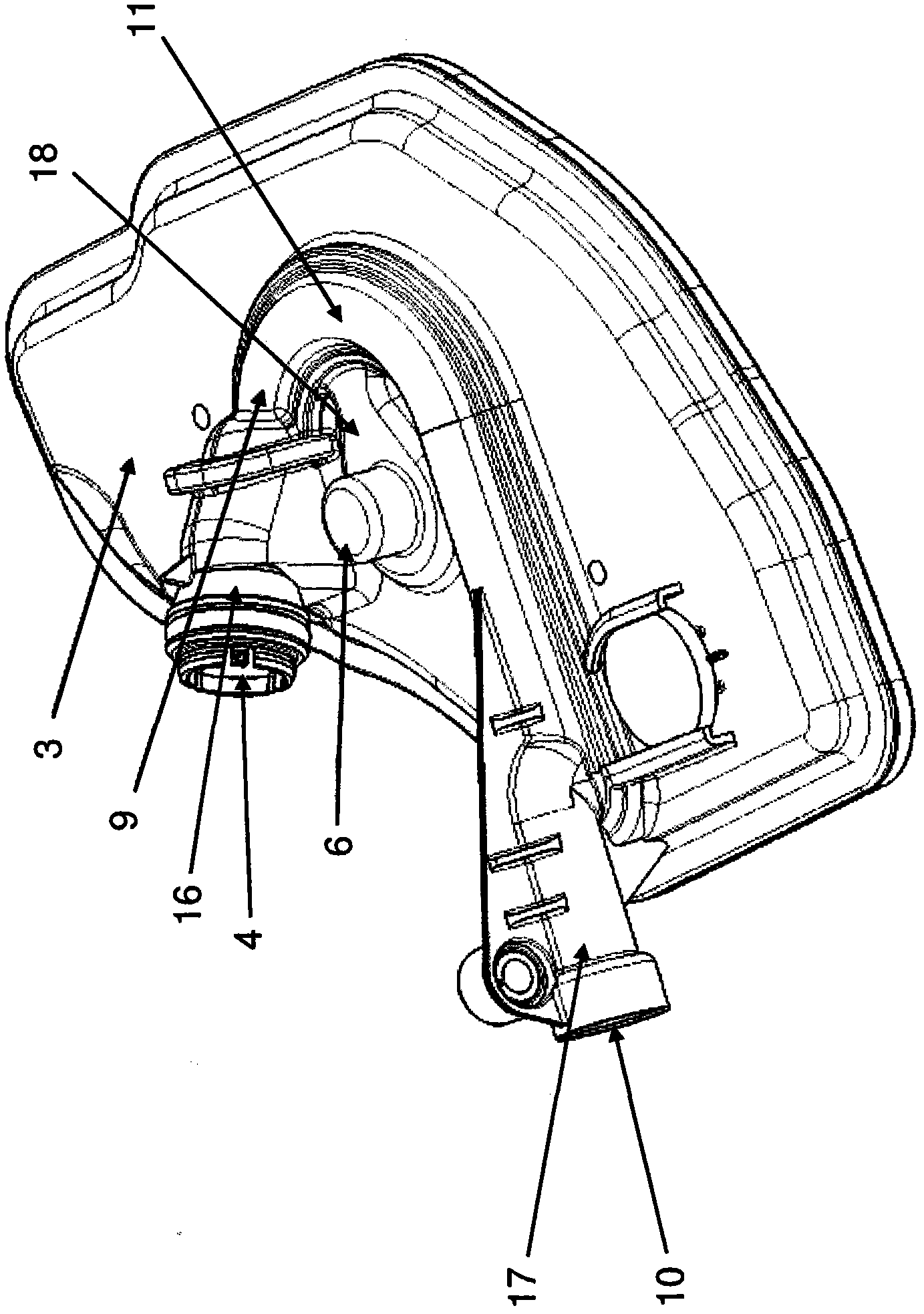
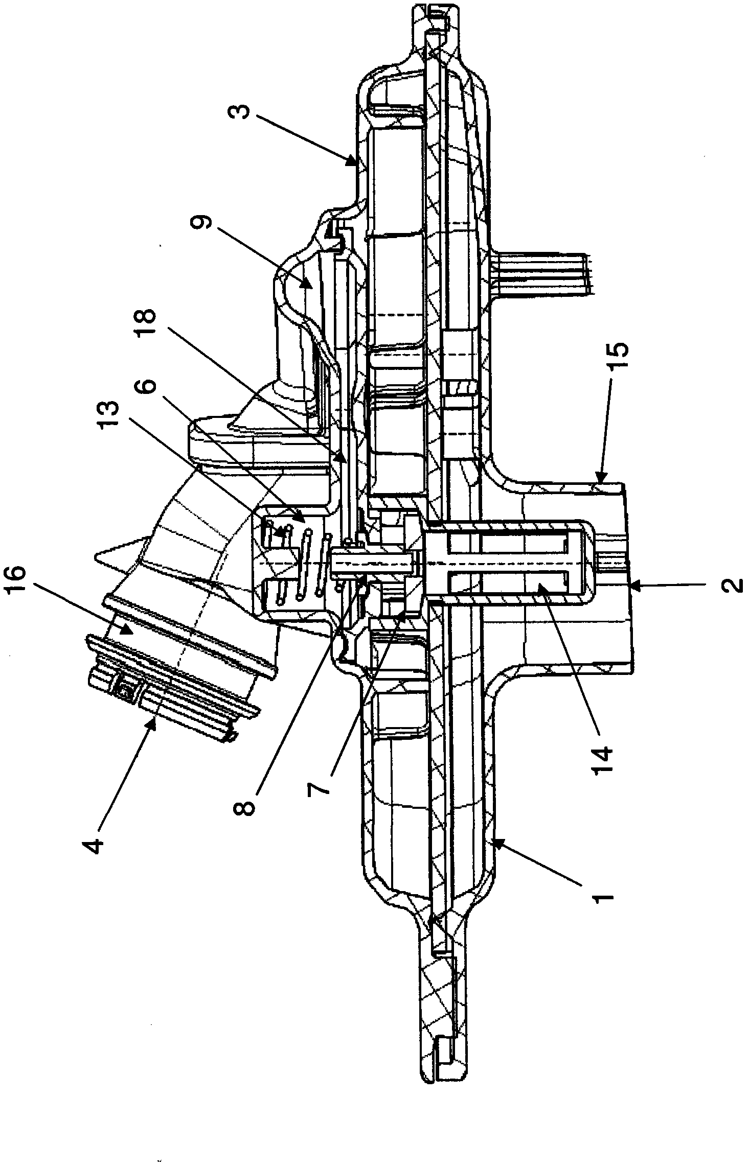
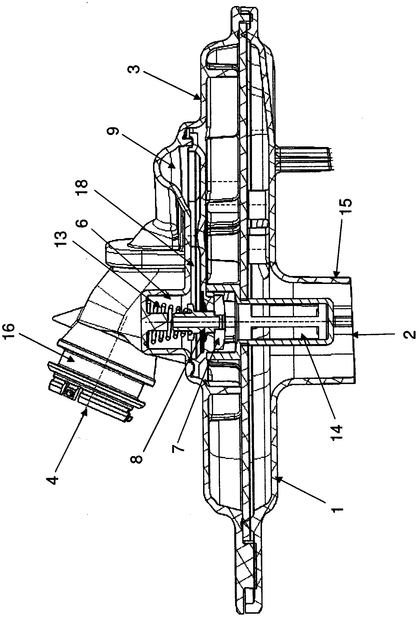
[0018] figure 1A possible embodiment of the oil suction filter according to the invention is shown in a perspective view looking at the upper side of the oil suction filter. This view shows the upper housing part 3 and part of the channel 9 integrated into the upper housing part 3 . In the example shown, channel 9 is a pressure channel for suction pressure boosting. When the channel 9 is configured as a closed channel to a certain extent, and only a part of the oil pumped through the oil outlet 4 by the pump not shown flows back to the channel 9, then also given according to the invention. figure 2 The control of the bypass valve 7 shown in , or more specifically its control piston 8 , wherein the oil pressure is related to the corresponding operating state of the oil suction filter. According to the example shown, the upper part of the channel 9 for the boosting of the suction pressure is formed here by a groove-like bead 11 on the upper side of the upper housing part 3 . ...


PUM


Abstract

The invention relates to an oil suction oil filter with a bypass (6). The oil suction filter consists of a filter housing and a filter medium (5), in which an oil inlet (2) is provided on the lower housing part (1) and an oil inlet (2) is provided on the upper housing part (3) An oil outlet (4) is arranged on it, and the filter medium is arranged in the filter housing between the oil inlet (2) and the oil outlet (4). In the bypass ( 6 ) formed relative to the filter medium ( 5 ), there is a bypass valve ( 7 ) designed as a regulating valve. For this purpose, the control piston (8) of the control valve (7), which opens or closes the bypass (6) depending on the operating state of the suction filter, is effectively connected to the channel (9) integrated into the upper housing part (3) connect. A part of the oil sucked in by the pump at the oil outlet (4) is guided back into this channel (9) via the return port (10), wherein the channel (9) is applied by the oil located in the overvoltage. The operative connection makes it possible to reliably close the bypass ( 6 ), at least when the oil guided back into the channel ( 9 ) has an overpressure, since this overpressure also acts on the control piston ( 8 ).

Description

technical field [0001] The invention relates to an oil suction oil filter. The invention relates to an oil suction filter which is used, for example, as part of an oil circuit for supplying a motor vehicle transmission with oil as the working medium. Such an oil suction filter has a bypass for its fine-meshed filter medium, by means of which the impurities contained in the oil are filtered out, said bypass when the oil is cold and therefore viscous or has a When the viscosity is high and the fine-meshed filter medium has a particularly high flow resistance for the oil, it is ensured that enough oil is supplied on the suction side of the filter for the suction pump to circulate the oil. suction. Background technique [0002] The oil suction filter according to the preamble essentially consists of a preferably disc-shaped lower housing part or housing lower part with a generally socket-shaped oil inlet and a likewise preferably disc-shaped housing with an outlet. The upper ...

Claims


Application Information

Patent Timeline
Patent Type & Authority Applications(China)
IPC IPC(8): B01D35/02B01D35/147
CPCF01M2001/1078B01D35/0273F01M2001/1092
Inventor M·罗森达尔S·布鲁萨T·克拉默D·金佩尔
Owner ZF FRIEDRICHSHAFEN AG
Why Eureka
Try Eureka